AC Input-DC Output Type Solid State Relay
AC Input-DC Output Type Solid State Relay, AC-DC Solid State Relay, can control DC load circuit through AC control signal.

AC Input-AC Output Type Solid State Relay
AC Input-AC Output Type Solid State Relay, AC-AC Solid State Relay, can control AC load circuit through AC control signal.
AC
The current magnitude and direction of Alternating Current (AC) change periodically with time, and the average value in one cycle is zero.
Absorption Circuit
Absorption Circuit, also known as snubber circuit, is an important protection circuit for power electronic components. The snubber circuit can be used not only for the protection of semi-controlled devices, but also for fully controlled devices (such as GTR, GTO, power MOSFET and IGBT).
The basic working principle of the snubber circuit is to suppress the current rise rate (di) of the device by utilizing the characteristic that the inductor current cannot be abrupt, and to suppress the voltage rise rate (dv) of the device by utilizing the characteristic that the capacitor voltage cannot be abruptly changed.
Zero Crossing Detector
Zero Crossing Detector consists of transistors or IC components to detect the load voltage of the solid state relays, only if the load voltage has crossed the zero, the detector will allow the solid state relays to switch the load.
Low Power Device
Low Power Device, also know as input device or control device, is the input signal source of the soild state relays. Solid state relays can control the large current device with the low power signal from the input device.
Terminology Library Location : Home > Terminology Library > Optoelectronic Isolation
Optoelectronic Isolation is a method to isolate the input and output signals physically and electrically by using light as a signal medium to minimize interference between the two signals. Solid state relays use opto-coupler as signal isolation method, so its EMC (the ability to control EMI) is better than mechanical relays.
Power
Power refers to the amount of work done by an object in a unit of time. That is, the power is a physical quantity that describes the speed of work, and can be divided into electric power and power.
The electric power is the physical quantity indicating the current work speed. The power of a electronic component is equal to the power consumed by it in 1 second (t, unit is s) (W, the unit is J), that is, P=W/t.
The magnitude of the electric power is also equal to the product of the voltage across the conductor and the current through the conductor: P = U*I.
For a purely resistive circuit, the calculation formula of electric power can also be expressed as: P=I^2*R and P=U^2 /R.
The electric power is the physical quantity indicating the current work speed. The power of a electronic component is equal to the power consumed by it in 1 second (t, unit is s) (W, the unit is J), that is, P=W/t.
The magnitude of the electric power is also equal to the product of the voltage across the conductor and the current through the conductor: P = U*I.
For a purely resistive circuit, the calculation formula of electric power can also be expressed as: P=I^2*R and P=U^2 /R.
Actuator
Actuator is a component of a machine that is responsible for moving and controlling a mechanism or system, for example by opening a valve. In simple terms, it is a "mover". In electronic and electrical systems, actuators are electric motor, solenoid valves, cylinder and etc.
Explosion Proof
In electrical engineering, hazardous locations are defined as places where fire or explosion hazards may exist due to flammable gases, flammable liquid–produced vapors, combustible liquid–produced vapors, combustible dusts, or ignitable fibers/flyings present in the air in quantities sufficient to produce explosive or ignitable mixtures. Electrical equipment that must be installed in such classified locations should be specially designed and tested to ensure it does not initiate an explosion, due to arcing contacts or high surface temperature of equipment. The solid state relays with better explosion proofing than that of mechanical relays can serve in the hazardous locations.
Insulation Resistance
Insulation Resistance is an ability of a device to protect against short circuit and electrical breakdown by using the Insulation Material. Solid state relays have better insulation resistance than mechanical relays.
Mechanical Shock Resistance
Mechanical Shock Resistance also known as shock proofing or toughness, is the ability of a material to absorb energy and plastically deform without fracturing. One definition of material toughness is the amount of energy per unit volume that a material can absorb before rupturing. It is also defined as a material's resistance to fracture when stressed. Solid state relays have better shock resistance than mechanical relays.
How to wire the MGR solid state relay? - 4.How to wire PCB Solid State Relay
§4. How to wire PCB Solid State Relay
-PCB Solid State Relay Wiring Diagram
4.1 PCB DC to DC Solid State Relay (SIP)
GJ-FA-L Series
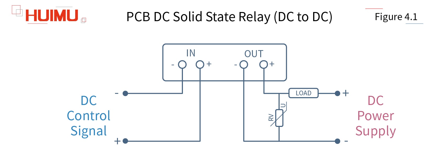
The SIP PCB mounting DC to DC solid state relay uses a DC signal to control the DC load. The input circuit of PCB mounting DC-DC solid state switch is connected to the DC control device. The output circuit is connected to the DC power supply and the load. The solid state relay uses the SIP 4-pin package and standard British PCB mounting dimensions.
Note: Before installation and use, please confirm whether the specifications (such as input current, input voltage, output current, output voltage and etc.) of the solid state relay meet the requirements of the application.
4.2 PCB DC to DC Solid State Relay (DIP)
JGX_FA Series
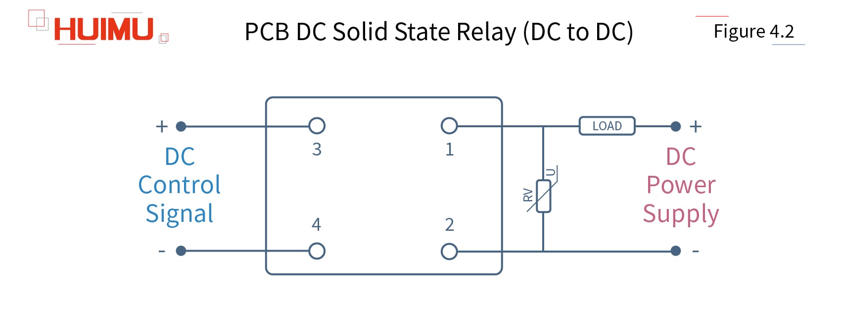
The DIP PCB mounting DC to DC solid state relay uses a DC signal to control the DC load. The input circuit of PCB mounting DC-DC solid state switch is connected to the DC control device. The output circuit is connected to the DC power supply and the load. The solid state relay uses the DIP 4-pin package and standard British PCB mounting dimensions.
Note: Before installation and use, please confirm whether the specifications (such as input current, input voltage, output current, output voltage and etc.) of the solid state relay meet the requirements of the application.
The circuit wiring diagram of the Heat Sink Type DIP PCB Mounting DC to DC Solid State Relay is the same as the DIP dc to dc solid state relay.
4.3 PCB DC to AC Solid State Relay (SIP)
GJ_L Series
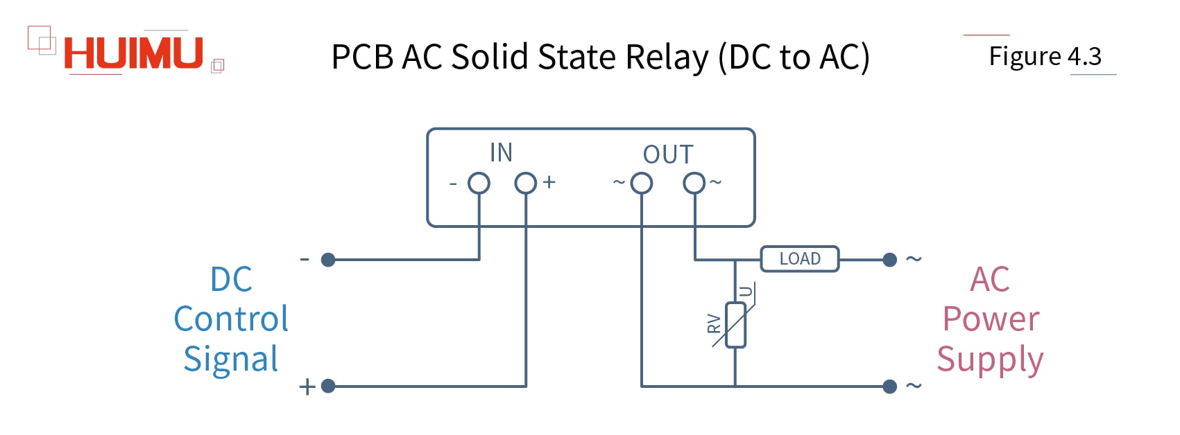
The SIP PCB mounting DC to AC solid state relay uses a DC signal to control the single phase AC load. The input circuit of PCB mounting DC-AC solid state switch is connected to the DC control device. The output circuit is connected to the single phase AC power supply and the load. The solid state relay uses the SIP 4-pin package and standard British PCB mounting dimensions.
Note: Before installation and use, please confirm whether the specifications (such as input current, input voltage, output current, output voltage and etc.) of the solid state relay meet the requirements of the application.
4.4 PCB DC to AC Solid State Relay (DIP)
JGX_F Series
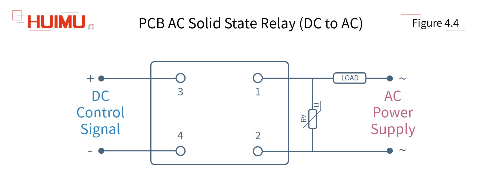
The DIP PCB mounting DC to AC solid state relay uses a DC signal to control the single phase AC load. The input circuit of PCB mounting DC-AC solid state switch is connected to the DC control device. The output circuit is connected to the single phase AC power supply and the load. The solid state relay uses the DIP 4-pin package and standard British PCB mounting dimensions.
Note: Before installation and use, please confirm whether the specifications (such as input current, input voltage, output current, output voltage and etc.) of the solid state relay meet the requirements of the application.
The circuit wiring diagram of the Heat Sink Type DIP PCB Mounting DC to AC Solid State Relay is the same as the DIP dc to ac solid state relay.
How to wire the MGR solid state relay? - 3.How to wire Industrial AC Solid State Relay
§3. How to wire Industrial AC Solid State Relay
-Industrial AC Solid State Relay Wiring Diagram
3.1 Industrial Single Phase DC to AC Solid State Relay
MGR-H Series
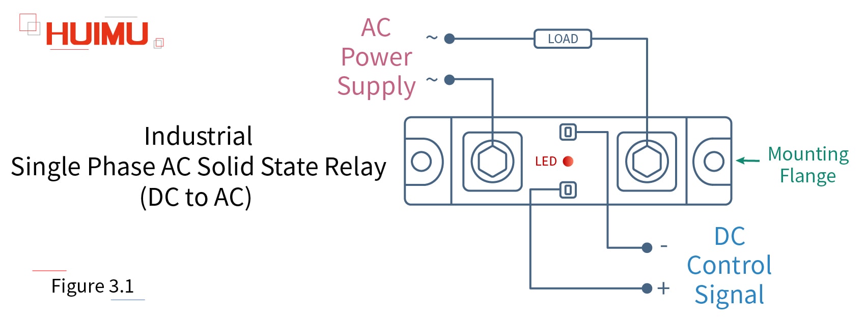
The standard type industrial DC to AC solid state relay is a four-terminal electronic device that uses a DC signal to control the single phase AC load. The input circuit of the industrial DC-AC solid state switch is connected to the DC control device. And LED indicators shows the working status. The output circuit is connected to a single phase AC load. The industrial single phase dc to ac SSR is installed in the application device by the standard mounting flange.
The circuit wiring diagram of the industrial random conduction DC to AC solid state relay (or industrial random fire dc to ac ssr) is the same as the zero-crossing dc to ac solid state relay.
Note: Before installation and use, please confirm whether the specifications (such as input current, input voltage, output current, output voltage and etc.) of the solid state relay meet the requirements of the application.
3.2 Industrial Single Phase AC to AC Solid State Relay
MGR-AH Series
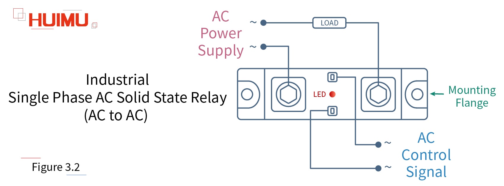
The standard type industrial AC to AC solid state relay is a four-terminal electronic device that uses a single phase AC signal to control the single phase AC load. The input circuit of the industrial AC-AC solid state switch is connected to the single phase AC control device. And LED indicators shows the working status. The output circuit is connected to a single phase AC load. The industrial single phase ac to ac SSR is installed in the application device by the standard mounting flange.
Note: Before installation and use, please confirm whether the specifications (such as input current, input voltage, output current, output voltage and etc.) of the solid state relay meet the requirements of the application.
3.3 Industrial Single Phase DC to AC Solid State Relay (High Current Type)
MGR-H Series
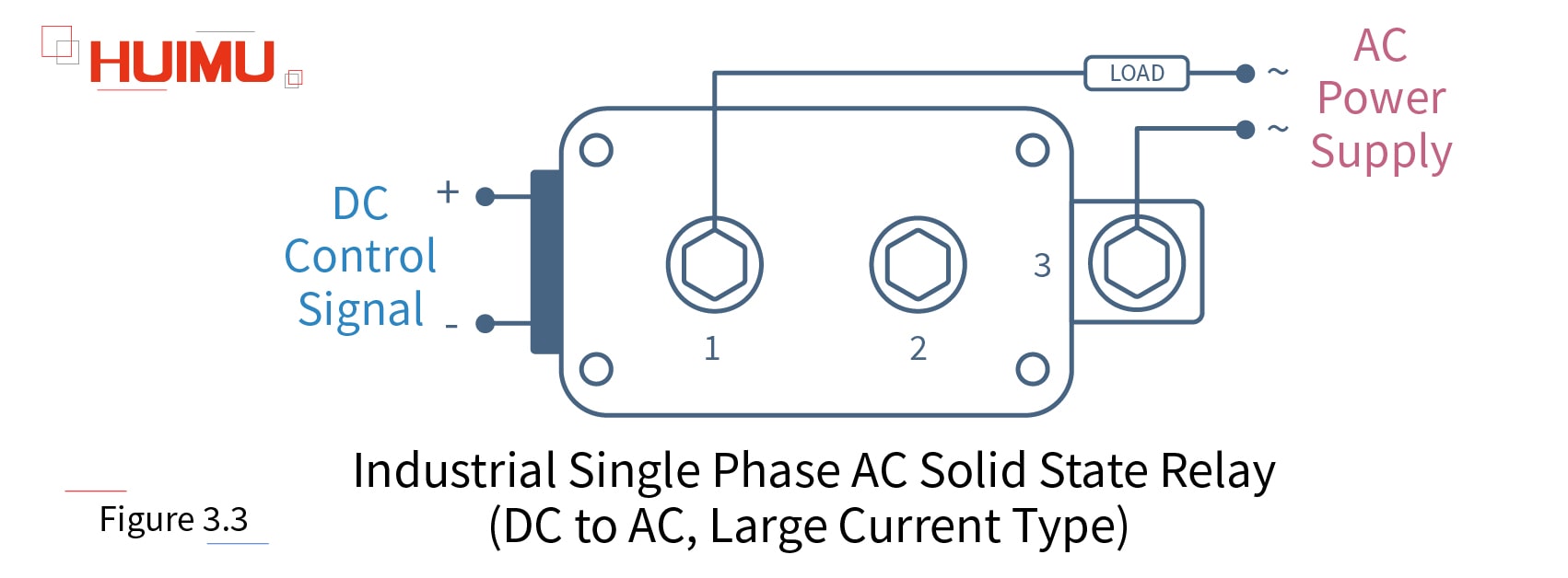
The large current type industrial DC to AC solid state relay uses a DC signal to control the single phase AC load. The input circuit is connected to the DC control device. The output circuit is connected to the single phase AC load through Port1 and Port3.
Note: Before installation and use, please confirm whether the specifications (such as input current, input voltage, output current, output voltage and etc.) of the solid state relay meet the requirements of the application.
3.4 Industrial Single Phase AC to AC Solid State Relay (High Current Type)
MGR-AH Series
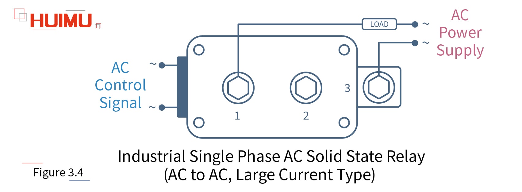
The large current type industrial AC to AC solid state relay uses a single phase AC signal to control the single phase AC load. The input circuit is connected to the single phase AC control device. The output circuit is connected to the single phase AC load through Port1 and Port3.
Note: Before installation and use, please confirm whether the specifications (such as input current, input voltage, output current, output voltage and etc.) of the solid state relay meet the requirements of the application.
3.5 Industrial Three Phase DC to AC Combined Solid State Relay
MGR-H_3 Series
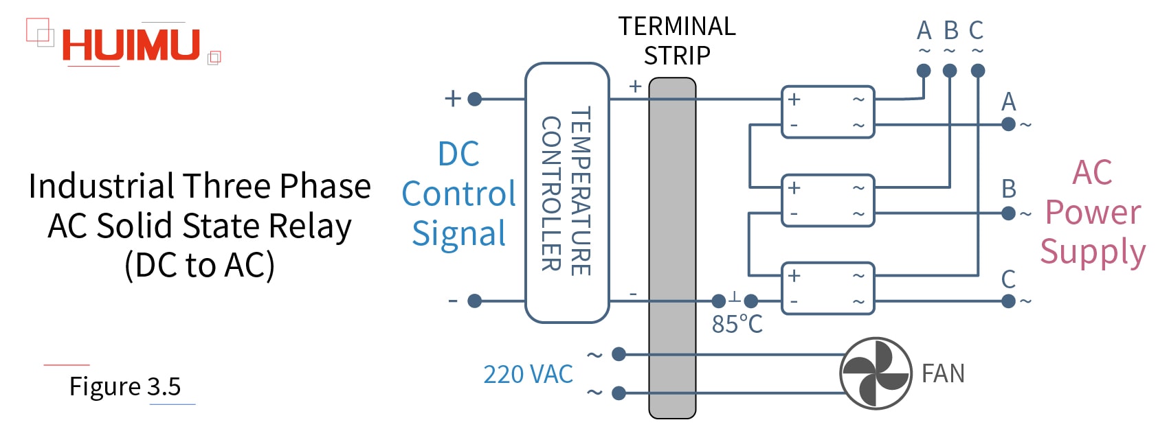
The combined type three phase industrial DC to AC solid state relay consists of three standard type DC to AC industrial solid state switches, a 220VAC fan, an 85°C temperature control switch and a heat sink. This type of three phase industrial SSR uses a DC signal to control the three phase AC load. The input circuit is connected to the DC control device. The output circuit is connected to the three phase AC power supply and load.
Note: Before installation and use, please confirm whether the specifications (such as input current, input voltage, output current, output voltage and etc.) of the solid state relay meet the requirements of the application.
3.6 Industrial Three Phase AC to AC Combined Solid State Relay
MGR-AH_3 Series
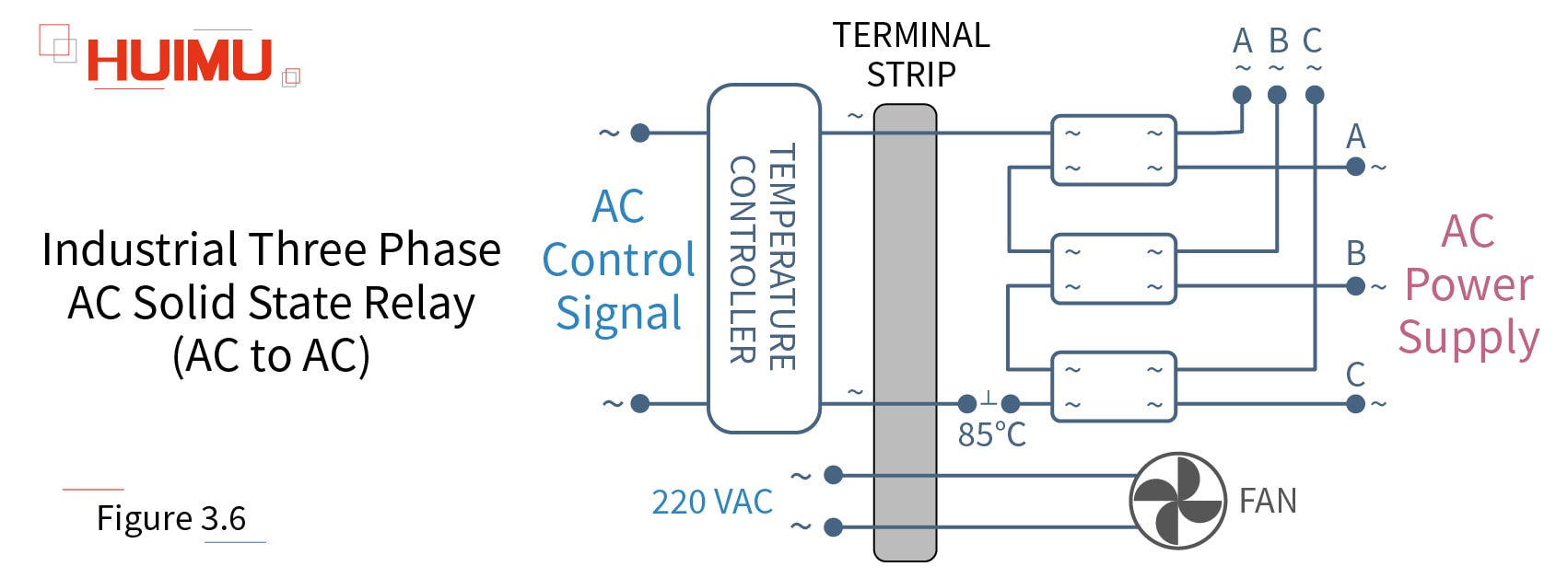
The combined type three phase industrial AC to AC solid state relay consists of three standard type AC to AC industrial solid state switches, a 220VAC fan, an 85°C temperature control switch and a heat sink. This type of three phase industrial SSR uses a single phase AC signal to control the three phase AC load. The input circuit is connected to the single phase AC control device. The output circuit is connected to the three phase AC power supply and load.
Note: Before installation and use, please confirm whether the specifications (such as input current, input voltage, output current, output voltage and etc.) of the solid state relay meet the requirements of the application.
How to wire the MGR solid state relay? - 2.How to Wire AC Solid State Relay
§2. How to Wire AC Solid State Relay
-AC Solid State Relay Wiring Diagram
2.1 Single Phase DC to AC Solid State Relay
MGR-1D Series
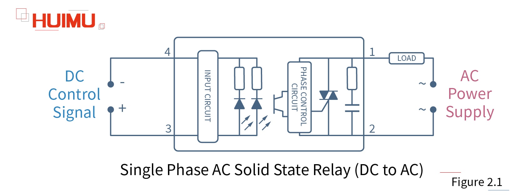
The single phase DC to AC solid state relay is a four-terminal electronic device that uses a DC signal to control the single phase AC load. Port1 and Port2 of DC-AC solid state switch are connected to the load and the single phase AC power supply. Port3 and Port4 are connected to the DC control device.
Note: Before installation and use, please confirm whether the specifications (such as input current, input voltage, output current, output voltage and etc.) of the solid state relay meet the requirements of the application.
The circuit wiring diagram of the Random Conduction DC to AC Solid State Relay (or random fire dc to ac ssr) is the same as the zero-crossing dc to ac solid state relay.
The circuit wiring diagram of the MINI DC to AC Solid State Relay is the same as the zero-crossing dc to ac solid state relay.
2.2 Single Phase AC to AC Solid State Relay
MGR-1A Series
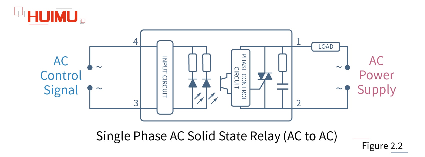
The single phase AC to AC solid state relay is a four-terminal electronic device that uses a single phase AC signal to control the single phase AC load. Port1 and Port2 of AC-AC solid state switch are connected to the load and the single phase AC power supply. Port3 and Port4 are connected to the single phase AC control device.
Note: Before installation and use, please confirm whether the specifications (such as input current, input voltage, output current, output voltage and etc.) of the solid state relay meet the requirements of the application.
2.3 Three Phase DC to AC Solid State Relay
MGR-3032 Series
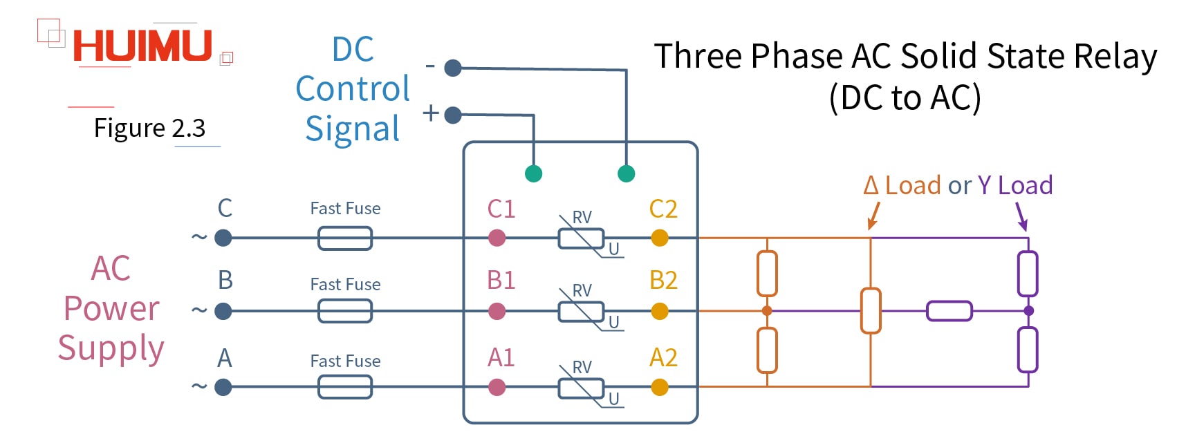
The three phase DC to AC solid state relay is an eight-terminal electronic device that uses a DC signal to control three phase AC load. A1, B1, and C1 of three phase DC-AC solid state switch are connected to the three phase AC power supply; A2, B2, and C2 are connected to the Δ load (delta load) or Y load. "+" and "-" are connected to DC control device.
Note: Before installation and use, please confirm whether the specifications (such as input current, input voltage, output current, output voltage and etc. ) of the solid state relay meet the requirements of the application.
The circuit wiring diagram of the Compact Three Phase AC to AC Solid State Relay is the same as the zero-crossing three phase ac to ac solid state relay.
2.4 Three Phase AC to AC Solid State Relay
MGR-3A Series
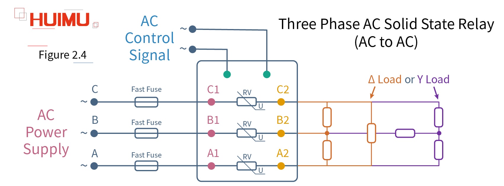
The three phase AC to AC solid state relay is an eight-terminal electronic device that uses a single phase AC signal to control three phase AC load. A1, B1, C1 of three phase AC-AC solid state switch are connected to the three phase AC power supply; A2, B2, and C2 are connected to the Δ load (delta load) or Y load. The input circuit of the three phase ac to ac SSR are connected to single phase AC control device.
Note: Before installation and use, please confirm whether the specifications (such as input current, input voltage, output current, output voltage and etc.) of the solid state relay meet the requirements of the application.
The circuit wiring diagram of the Compact Three Phase AC to AC Solid State Relay is the same as the zero-crossing three phase ac to ac solid state relay.
How to wire the MGR solid state relay? - 1.How to Wire DC Solid State Relay
§1. How to Wire DC Solid State Relay
-DC Solid State Relay Wiring Diagram
1.1 DC to DC Solid State Relay
MGR-1DD Series
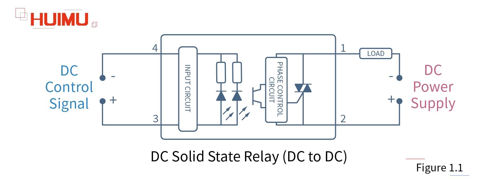
The DC to DC solid state relay is a four-terminal electronic device that uses a DC signal to control the DC load. Port1 and Port2 of DC-DC solid state switch are connected to the load and the DC power supply. Port3 and Port4 are connected to the DC control device.
Note: Before installation and use, please confirm whether the specifications (such as input current, input voltage, output current, output voltage and etc.) of the solid state relay meet the requirements of the application.
The circuit wiring diagram of the MINI DC to DC Solid State Relay is the same as the zero-crossing dc to dc solid state relay.
1.2 AC to DC Solid State Relay
MGR-1AD Series
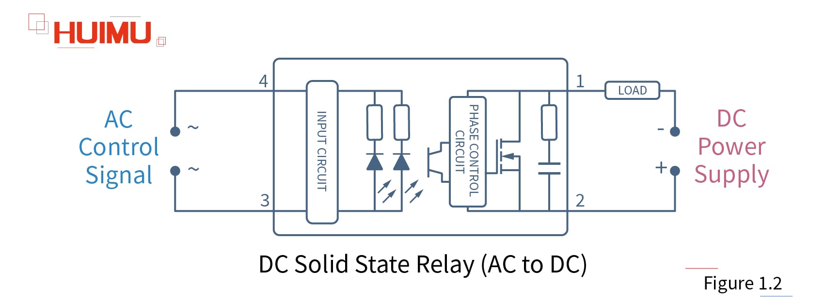
The AC to DC solid state relay is a four-terminal electronic device that uses an AC signal to control the DC load. Port1 and Port2 of AC-DC solid state switch are connected to the load and the DC power supply. Port3 and Port4 are connected to the AC control device.
Note: Before installation and use, please confirm whether the specifications (such as input current, input voltage, output current, output voltage and etc.) of the solid state relay meet the requirements of the application.
Arc - Short essay
An electric arc is a gas discharge phenomenon in which an electric current is generated by a momentary spark generated by some insulating medium such as air.
Spark - Short essay
 Spark is a kind of particulate matter with energy and heat generated by a large amount of electric energy when the contacts of mechanical relays strike together.
Moisture Resistance - Short essay
Moisture Resistance also known as damp proofing ability, is a type of moisture control to prevent the intrusion of humid air (water vapor) into the relay, causing corrosion of mechanical components, short-circuiting of electronic components and etc. Since the solid state relay uses a well-sealed casing, it has better moisture resistance than mechanical relays.
Insulation Material - Short essay
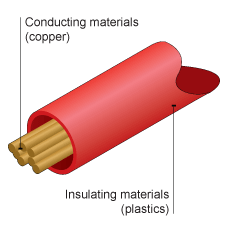 Insulation Material is the material for electric insulation use in the electrical and electronic field.
Subscribe to:
Posts (Atom)
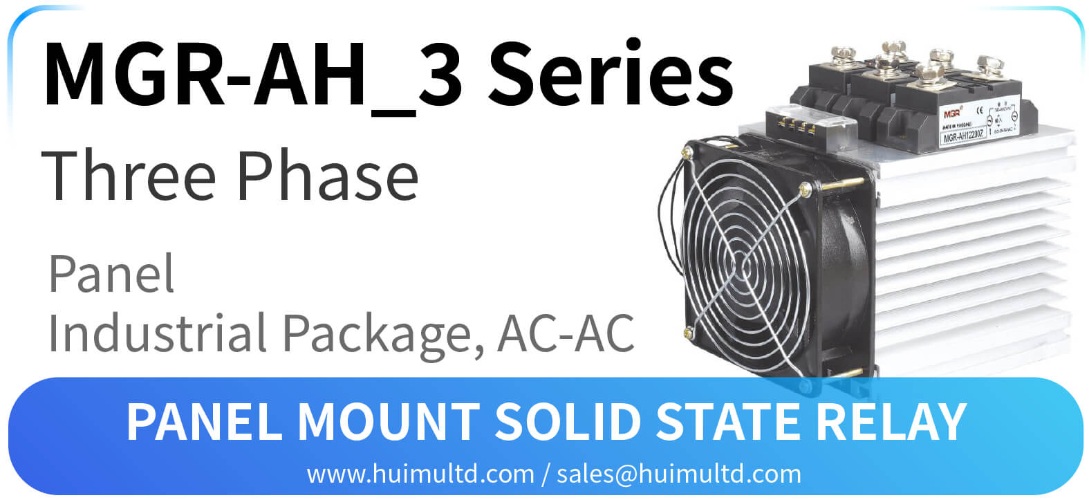
MGR-AH_3 Series Panel Mount Solid State Relay
MGR-AH_3 Series Panel Mount Solid State Relay [All the information on this website is for reference only, and the actual product and the a...
-
DF Series Intelligent Liquid Level Controller Introduction DF series intelligent high and low liquid level controllers with built-in int...
-
§3. How to wire Industrial AC Solid State Relay -Industrial AC Solid State Relay Wiring Diagram 3.1 Industrial Single Phase DC to AC Solid S...
-
KG316T Series Digital Programable Time Switch (Multiple Output) Introduction KG316T series timer switch can automatically turn on or off...


