§4. How to wire PCB Solid State Relay
-PCB Solid State Relay Wiring Diagram
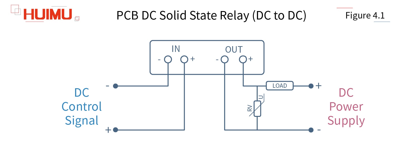
4.1 PCB DC to DC Solid State Relay (SIP)
GJ-FA-L Series

The SIP PCB mounting DC to DC solid state relay uses a DC signal to control the DC load. The input circuit of PCB mounting DC-DC solid state switch is connected to the DC control device. The output circuit is connected to the DC power supply and the load. The solid state relay uses the SIP 4-pin package and standard British PCB mounting dimensions.
Note: Before installation and use, please confirm whether the specifications (such as input current, input voltage, output current, output voltage and etc.) of the solid state relay meet the requirements of the application.
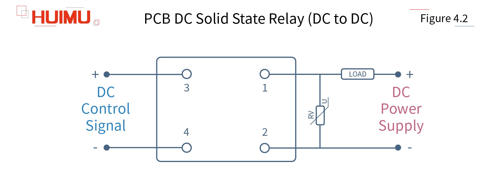
4.2 PCB DC to DC Solid State Relay (DIP)
JGX_FA Series

The DIP PCB mounting DC to DC solid state relay uses a DC signal to control the DC load. The input circuit of PCB mounting DC-DC solid state switch is connected to the DC control device. The output circuit is connected to the DC power supply and the load. The solid state relay uses the DIP 4-pin package and standard British PCB mounting dimensions.
Note: Before installation and use, please confirm whether the specifications (such as input current, input voltage, output current, output voltage and etc.) of the solid state relay meet the requirements of the application.
The circuit wiring diagram of the Heat Sink Type DIP PCB Mounting DC to DC Solid State Relay is the same as the DIP dc to dc solid state relay.
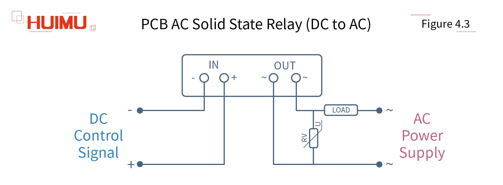
4.3 PCB DC to AC Solid State Relay (SIP)
GJ_L Series

The SIP PCB mounting DC to AC solid state relay uses a DC signal to control the single phase AC load. The input circuit of PCB mounting DC-AC solid state switch is connected to the DC control device. The output circuit is connected to the single phase AC power supply and the load. The solid state relay uses the SIP 4-pin package and standard British PCB mounting dimensions.
Note: Before installation and use, please confirm whether the specifications (such as input current, input voltage, output current, output voltage and etc.) of the solid state relay meet the requirements of the application.
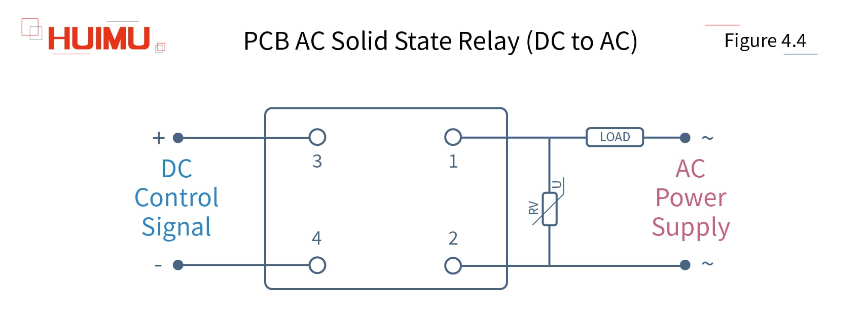
4.4 PCB DC to AC Solid State Relay (DIP)
JGX_F Series

The DIP PCB mounting DC to AC solid state relay uses a DC signal to control the single phase AC load. The input circuit of PCB mounting DC-AC solid state switch is connected to the DC control device. The output circuit is connected to the single phase AC power supply and the load. The solid state relay uses the DIP 4-pin package and standard British PCB mounting dimensions.
Note: Before installation and use, please confirm whether the specifications (such as input current, input voltage, output current, output voltage and etc.) of the solid state relay meet the requirements of the application.
The circuit wiring diagram of the Heat Sink Type DIP PCB Mounting DC to AC Solid State Relay is the same as the DIP dc to ac solid state relay.
