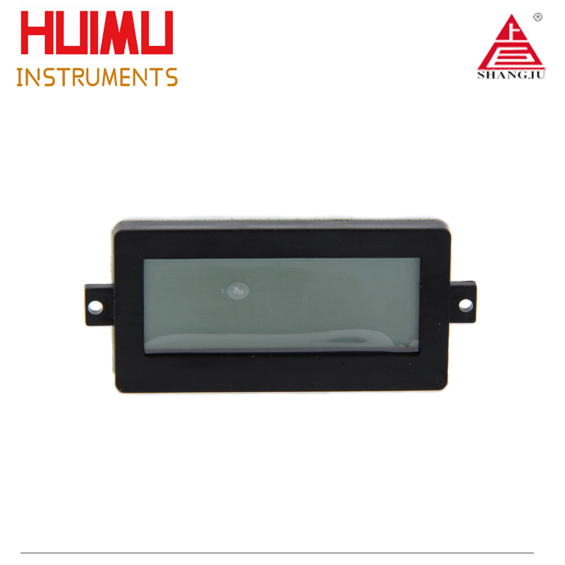
Intelligent Liquid Level Controller
Intelligently control the liquid level
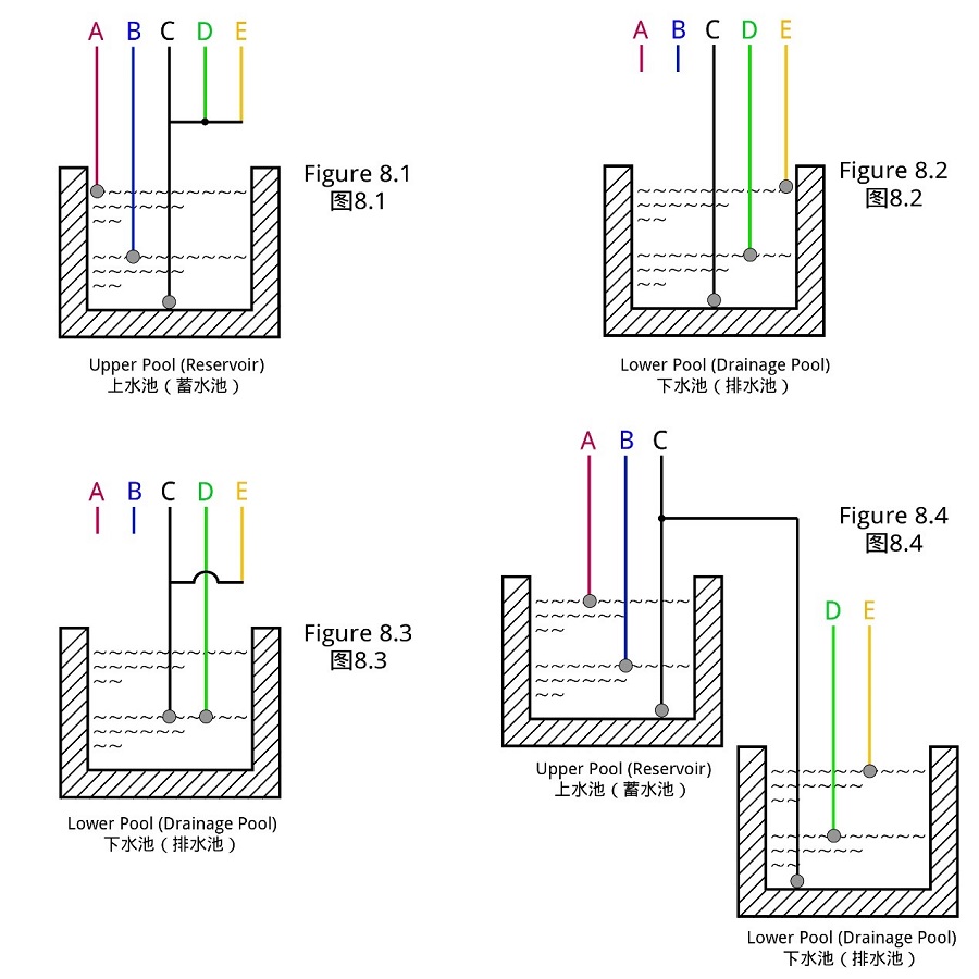
The intelligent liquid level controller (or high and low liquid level intelligent controller) uses integrated circuits as core chip, and has the functions of joint control of upper and lower pools, pool drainage and water shortage protection. It can realize automatic water replenishment and drainage of the water tank, and can effectively prevent the pool from overflowing or overflowing idling damage. Intelligent liquid level controllers are widely used in the fields of printing, dyeing, chemical industry, food, beverages, wine making, sugar making, etc., and are also very suitable for water supply systems of water pools (wells) in towns, rural areas, schools, industrial and mining enterprises and households.
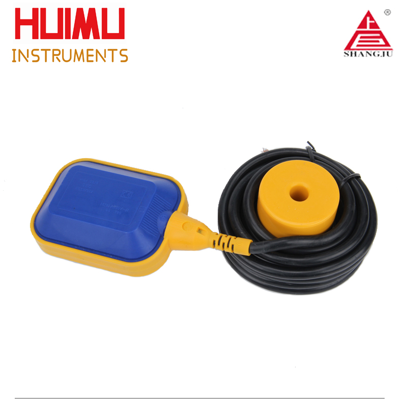
The float control switch (also known as float controller, cable float switch, plastic water level controller) is a switch that can adjust the liquid level in a pool, bucket, tank or well. It has the advantages of automatic adjustment, easy operation, easy installation, safety and reliability, maintenance-free, non-toxic and environmental protection, etc. It is also resistant to sewage and can be used in weak acid and weak alkali pools. Float controllers are widely used in fields such as printing, dyeing, chemicals, factories, and mines.
The following on this page provides the basic information of the intelligent liquid level controller. If you are interested in one of these products, you can click the "Product Number" or " More" to get more information.
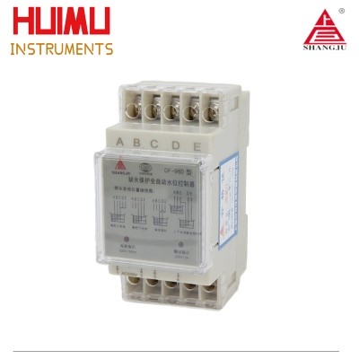
DF Series
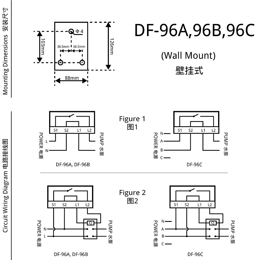
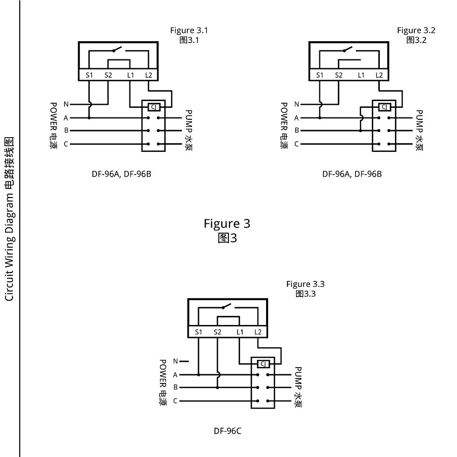
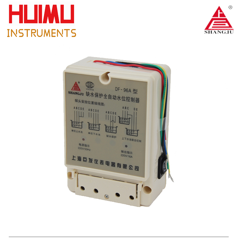
DF-96A/96B/96C
Operation Voltage: DF-96A/96B/96C: AC220V; DF-96C: AC380V; 50/60Hz (or other customized voltage)
Switching Capacity: 16A (DF-96A), 20A (DF-96B/C); COS=0.9
Signal distance: ≤30m(the cable length can be customized according to specific requirement)
More
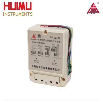
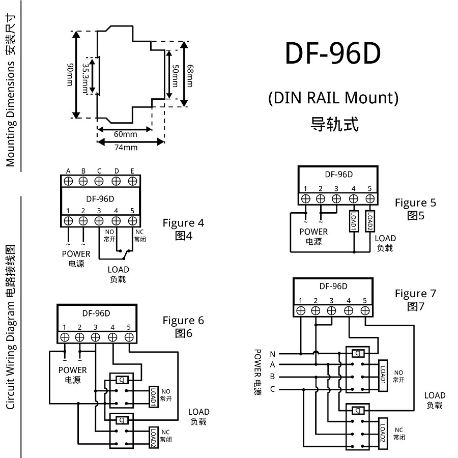
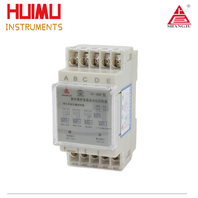
DF-96D
Operation Voltage: AC200V±10%,50/60Hz
Signal distance: ≤150m (the cable length can be customized according to specific requirement)
Switching Capacity: 5A; COS=0.9
More
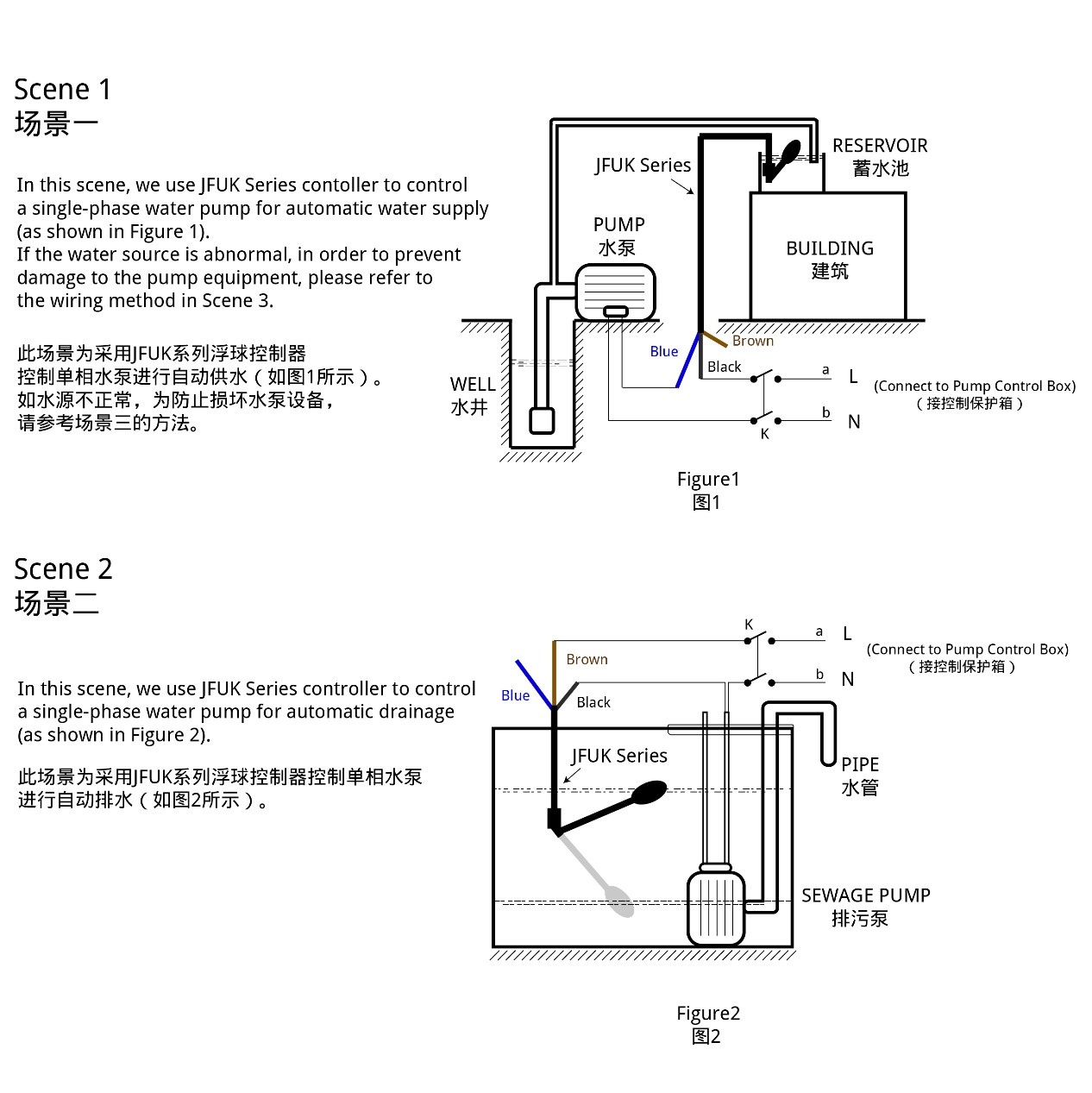
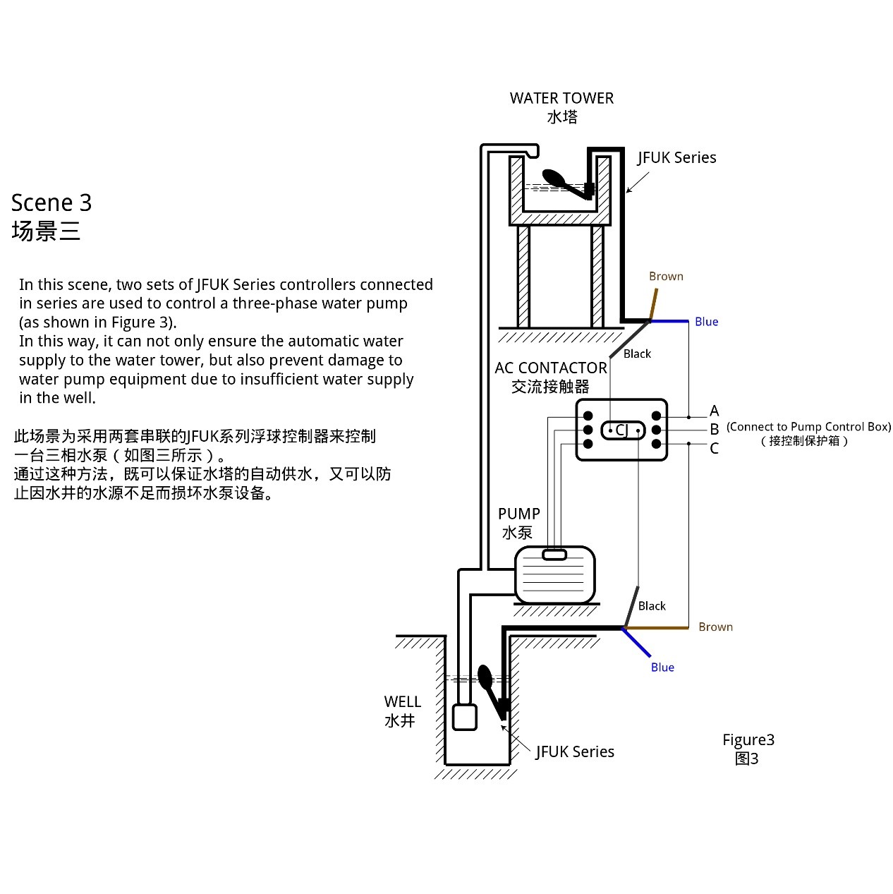
JFUK Series
JF-UK221 (Plastic)
Operation Voltage: 220VAC, 380VAC/50Hz
Rated Current: 8A(220VAC); 4A(380VAC);COS=0.9
Cable Length: 4 meters (the cable length can be customized according to specific requirement)
Operation Temperature: 0℃~80℃
Mechanical life: ≥5000 times
Liquid Level Control Range: ≥0.2 meter
More
JF-UK304 (Stainless Steel)
Operation Voltage: 220VAC, 380VAC/50Hz
Rated Current: 8A(220VAC); 4A(380VAC);COS=0.9
Cable Length: 4 meters (the cable length can be customized according to specific requirement)
Operation Temperature: 0℃~120℃
Mechanical life: ≥5000 times
Liquid Level Control Range: ≥0.2 meter
More