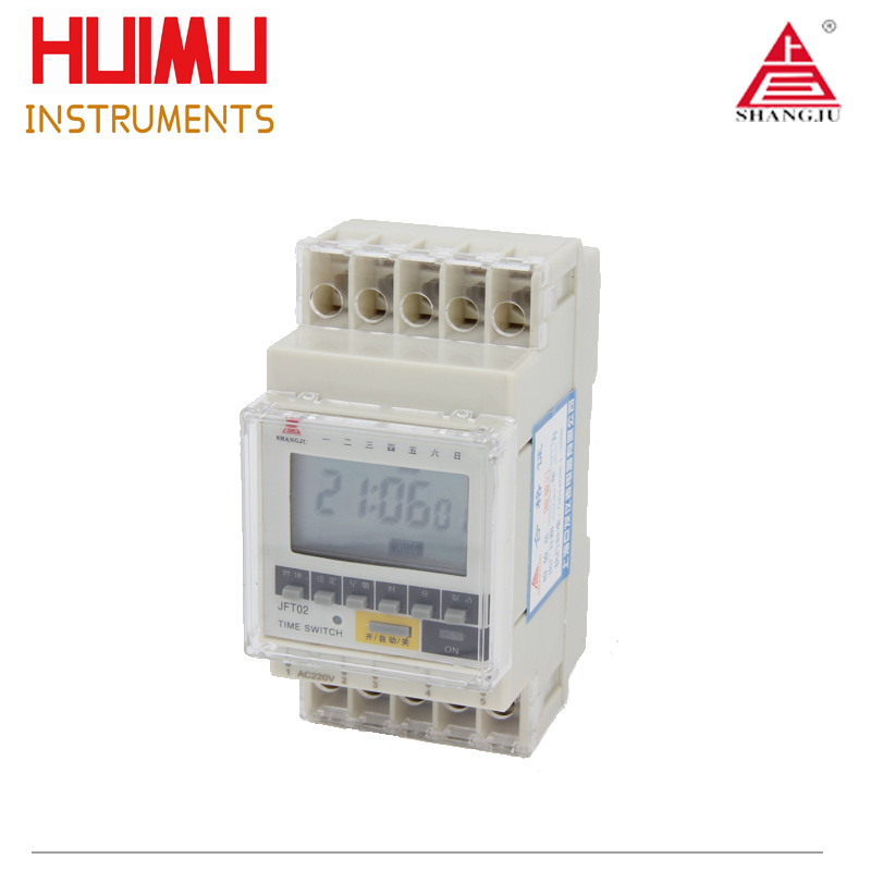
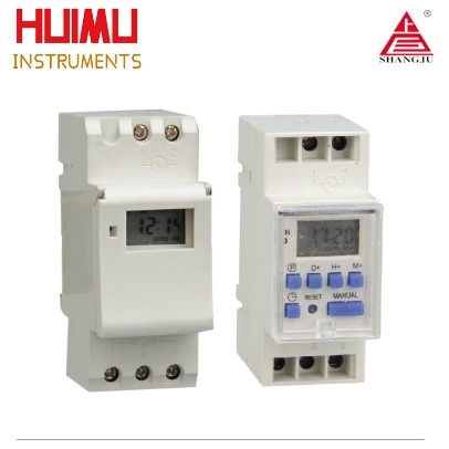
JFT-02
Digital Programable Time Switch (DIN Rail Mount)
Introduction
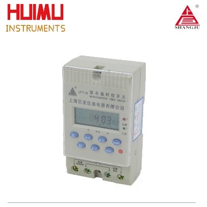
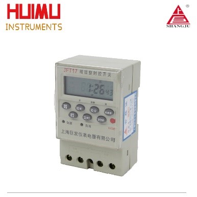
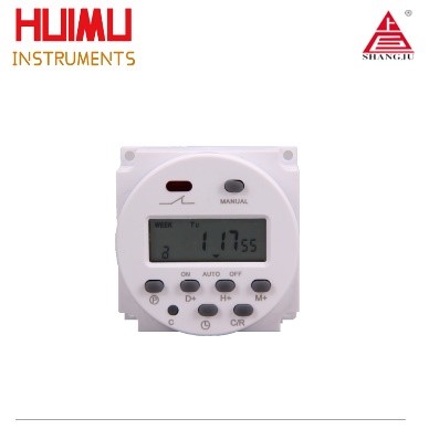
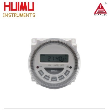
JFT02 series microcomputer time control switch is specially designed for DIN Rail Mount installation. It can be directly installed into the power distribution cabinet, meter box, signal box, etc., and used with other electrical equipment to achieve efficient control of the load JFT02 series digital time-controlled switch is consisted of digital LCD display, programmable IC chip, buttons, switching components and etc. JFT02 series digital timer switch is widely used in street lights, neon lights, advertising signs, production equipment, assembly lines, and broadcast equipment. The new version JFT02 adopts a brand-new chip technology, which can effectively avoid the false welding and missing welding. Besides, the all-new designed JFT02 has the characteristics of stable performance, low power consumption, light weight, and etc. The JFT02 series has two sub-series. JFT02-1a adopts single pole single throw switching plan (SPST), with only one normally open contact, which can control the switching state of a load; JFT02-1c adopts double pole double throw switching plan (SPDT), which has One normally open contact and one normally closed contact can simultaneously control the switching state of two loads.
Parameters
JFT02 (DIN Rail Mount)
Timer Range: 1min≤t≤168h (cycle work daily or weekly)
Operation Voltage: 110VAC, 220VAC/50Hz (or other customized voltage)
Operation Temperature: -10℃~ 60℃
Operation Humidity: <95%
Switching Capacity: 30A (resistive load), 15A (inductive load)
Contact Type: JFT02-1a (SPST, only 1 NO contact); JFT02-1c (SPDT, 1 NO and 1 NC contact)
Number of Settings: 10 groups per day
Control Mode: Manual, Auto
Consumption Power: ≤5W
Battery: 8AA battery
Time Error: ≤2s/day (25℃)
Dimensions: 100×50×74mm
Mounting: Wall/Rail
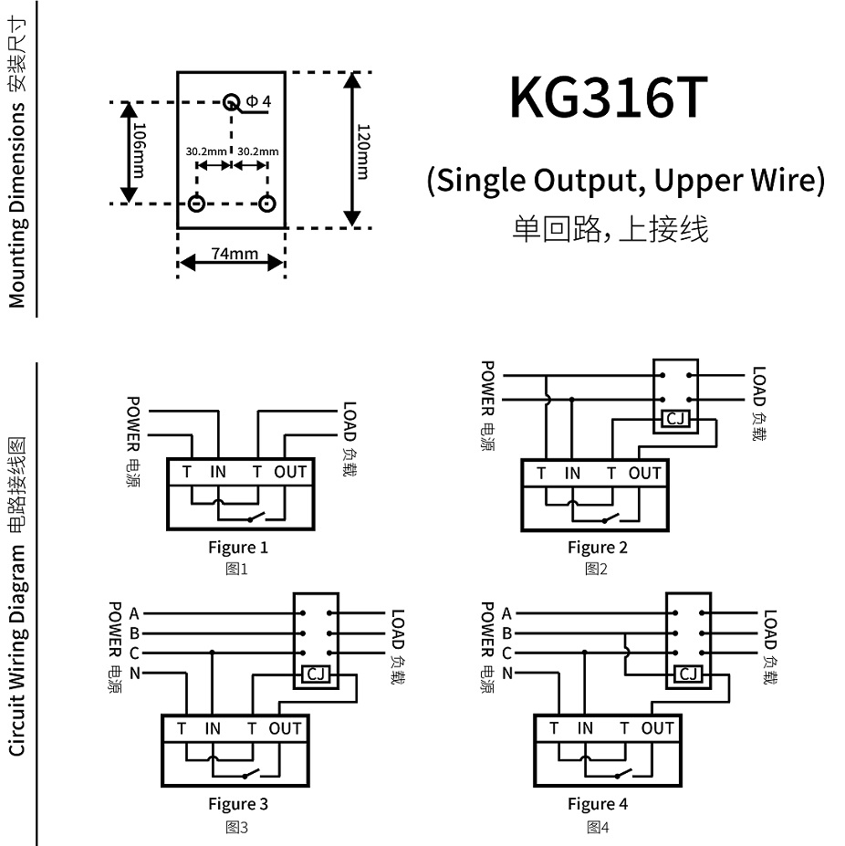
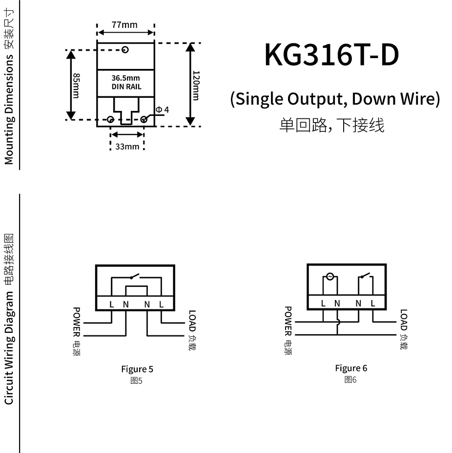
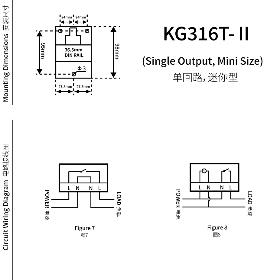
Dimensions & Wiring Diagram
JFT02 (DIN Rail Mount)
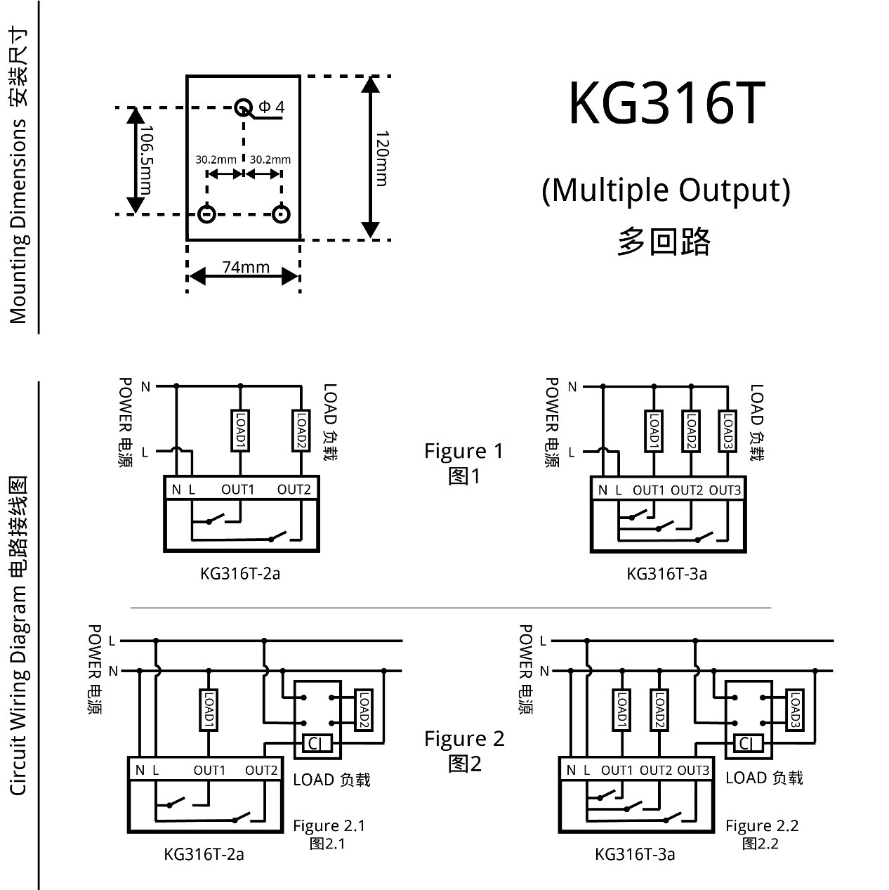
JFT02 has two sub-series (as shown in Figure 1): JFT02-1a has one normally open contact (PORT4); JFT02-1c has one normally open contact (PORT4) and one normally closed contact (PORT5).
1 Single Phase Power Supply
1.1 Direct control method (as shown in Figure 2)
Applicable objects: Loads with single-phase power supply, and the power consumption does not exceed the rated switching capacity of the timer switch.
1.2 Single-phase expansion method
Applicable objects: load with single-phase power supply, but the power consumption exceeds the rated switching capacity of the timer switch. This method should be adopted for inductive loads.
If this wiring method is adopted, the output terminal of the digital timer switch needs to be connected to a single phase AC contactor whose switching capacity should larger than the power consumption of the load to expanse the switching capacity of the timer switch.2 Three Phase Power Supply
Applicable objects: load with three-phase power supply (as shown in Figure 3).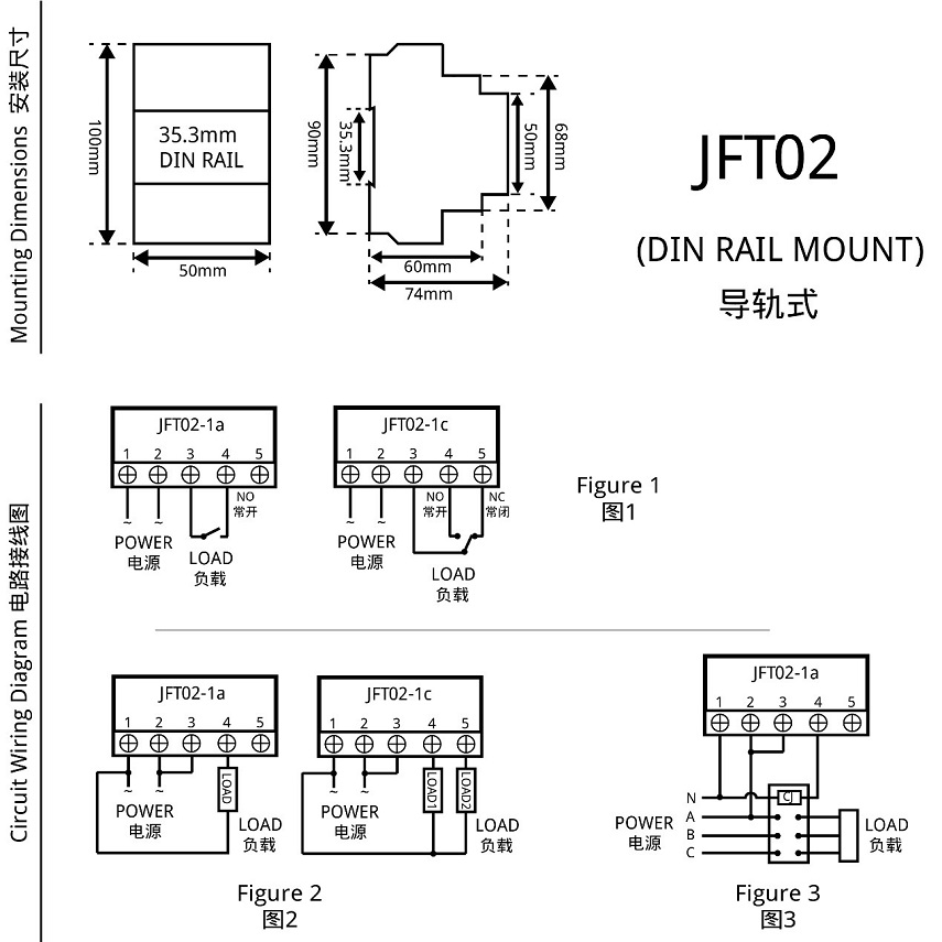
JFT02 dimensions and wiring diagram
Instructions For Use (How to set)
Please make sure that you have understood the functions of all the buttons on the panel (button area), and perform the actual operation according to the instructions.
1 Description of buttons and indicators
CLOCK (
): Press to display your local time (it should be set by yourself: you can press and hold the "CLOCK" key to enter the "Time Adjustment Mode", and adjust the "WEEK", “HOUR”, and “MINUTE” key to set the local time). PS: If no operation is performed within 30 seconds, the timer switch will automatically display the local time.
TIMER(): Press to enter the "Editing Mode", and then set the time to switch the load by adjusting the "WEEK", “HOUR”, and “MINUTE” key.
WEEK (D+): Adjust week or day. There are various working modes, such as "Five-day Mode" (Monday to Friday), "Six-day Mode" (Monday to Saturday), "Weekend Mode" (Saturday, Sunday), “Daily Mode" (Monday to Sunday), and "Three-day Mode" (Mon-Wed-Fri; Tue-Thu-Sat; Mon-Tue-Wed; Thu-Fri-Sat).
HOUR (H+): Adjust hour.
MINUTE (M+): Adjust minute.
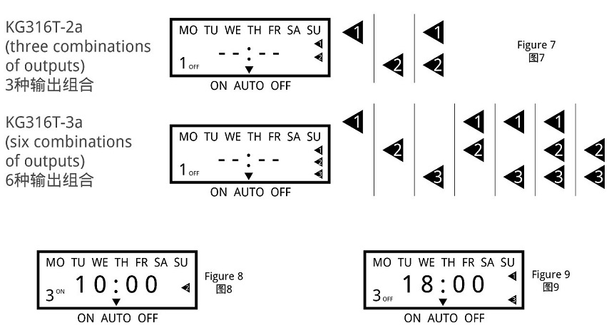
AUTO/MANU (MANUAL): Switch the three switching mode of "ON", "AUTO" and "OFF". For multiple-output timer switches, the output combination can be configured through the "AUTO/MANU" key when in the "Editing Mode"
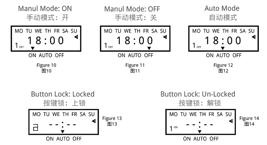
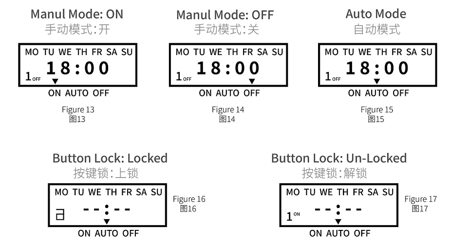
RESET/RECALL (Cancel/Restore, C/R): Press to cancel or restore the timing setting. PS: For products with button lock function, press the " RESET/RECALL " key four times to lock or unlock all buttons.
C: Long press the "C" key to clear all settings of the timer switch.
POWER LED: When the Power LED (red) is on, it means that the timer switch has been successfully connected to the power source.
WORK LED: When the Power LED (red) and the Work LED (green) are on at the same time, it means that the load is powered on.2 Operating instructions
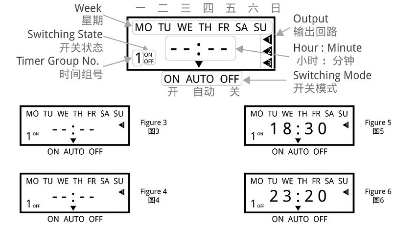
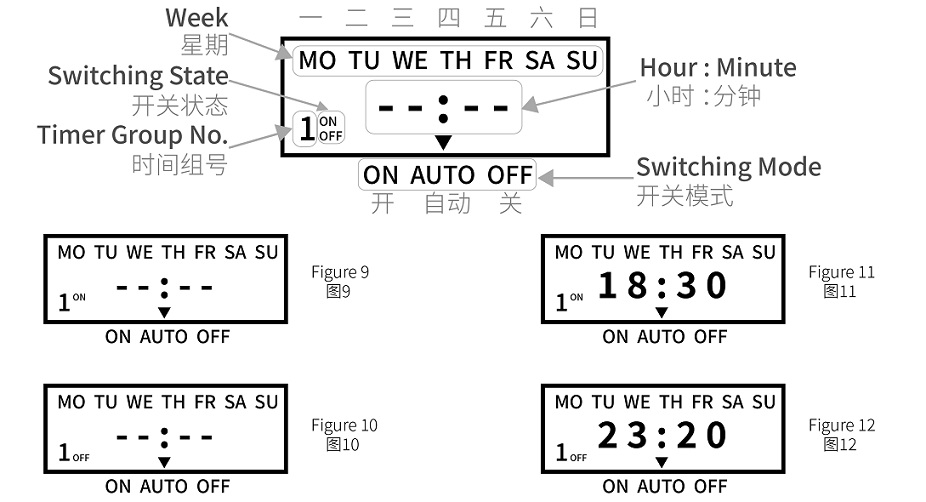
Step 1. Timing setting (on)Press the " TIMER " button to enter the "Editing Mode". At this time, the "1ON" symbol will appear at the bottom left of the LCD screen (that is, the first time to turn on the load, as shown in Figure 4), and then press the "WEEK" to select Working Mode, and then press the "HOUR" and "MINUTE" keys to input the required switching on time.
Step 2. Timing setting (off)Press the " TIMER " button again, the "1OFF" symbol will appear at the bottom left of the LCD screen (that is, the first time to turn off the load, as shown in Figure 5), and then press the "WEEK" to select Working Mode, and then press the "HOUR" and "MINUTE" keys to input the required switching off time. At this time, the first group of timing setting has been completed.
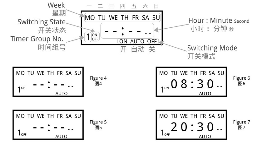
Timing Setting1
Step 3. Timing setting (number of groups)After completing the first group of timing setting, press the "TIMER" button again, the LCD display will show the "2ON" symbol, and you can set the second set of time setting. According to actual needs, you can repeat steps 1 and 2 to set many groups (the maximum programmable group number depends on the product's built-in chip). If you want to exit the “Editing Mode”, you can press the "CLOCK" key to exit it.
Step 4. RESET/RECALLAfter setting a group of time, for example, turn on the load at 18:30 every day (Figure 6), and turn off the load at 23:20 every day (Figure 7). If you want to cancel this group, you can press the "RESET/RECALL" button to delete this group of time settings. At this time, the group of time will be reset to the initial state, that is, "--: --" (Figure 4 and Figure 5). Under certain conditions (without any key operation or switching to other interfaces within 20 seconds after cancel operation), just press the "RESET/RECALL" button again to restore this group of time settings.
Step 5. AUTO/MANUThe timer switch has two switching modes: automatic and manual. In the automatic mode, the timer switch will be set according to the timing of steps 1 to 3, and the load will be automatically turned on or off at the corresponding time without human intervention. In manual mode, the load must be turned on or off by manual adjustment.
The specific operations are as follows:
1) If you need to turn on the load manually, you can click the "AUTO/MANU" button to switch the "▼" symbol on the display to the "ON" position (Figure 8). At this time, the load will always be in the on state and cannot be turned off automatically.
2) If you need to turn off the load manually, you can click the "AUTO/MANU" button to switch the "▼" symbol on the display to the "OFF" position (Figure 9). At this time, the load will always be in the off state and cannot be turned on automatically.
3) If you need to switch the load automatically, you can click the "AUTO/MANU" button to switch the "▼" symbol on the display to the "AUTO" position (Figure 10). At this time, the working state of the load will be switching automatically according to the timing setting, without being interfered by humans.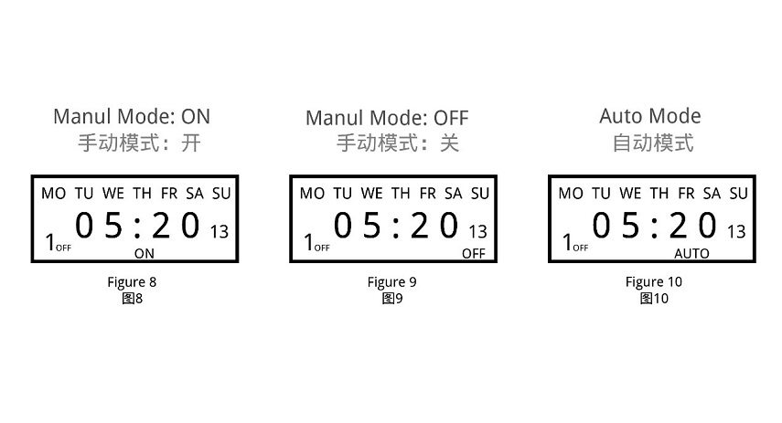
Timing Setting2
When you think there is a fault (FAQs)
Note: When the product fails, please disconnect the power first, and then check the equipment!
1 Check the week
If the timer switch does not turn on or turn off the load at the set time, it may be that the "WEEK" is not adjusted correctly, please check or reset it according to the method introduced in "Timing Setting".
2 Check the time groups
If the first point is confirmed to be correct, but the load still cannot be switched correctly on time, the reason will be that the extra time group has not been cancelled. Please refer to the method introduced in "Timing Setting" to delete it. PS: Only when the display shows "--: --", it means the time group is deleted successful; if it displays "00:00", it means 0 o'clock (24 o'clock), not the deleting success.
3 Check the switching mode
If the above two points are confirmed to be correct, but the timer switch still does not work normally, it may be that the timer switch is working in "Manual Mode". You can first adjust the "AUTO/MANU" key to set the timer switch to the right working state of the load (ON or OFF), then switch to the "Automatic Mode".
4 Check the fuse
If the above three points are correct and the timer switch still cannot work normally, please open the rear seat insurance cover (terminal cover) and check whether the fuse has been blown. If it is blown, please replace with a new 0.1A~0.3A fuse.
5 Check the power supply
If the Work LED (or Output LED) is on when the timer switch is working, but the load cannot be switched normally, please check whether the voltage of the power supply is too low. If the timer switch is burned out, please check whether the power supply voltage exceeds the rated voltage of the product and whether the power cable is connected incorrectly.
6 Please replace the battery
If the LCD screen does not display or the display is not clear, replace the battery with the same specification. (Only for timer switch with replaceable batteries)
7 Please contact us or local distributor
If the fault cannot be eliminated by the above methods, please contact us or the distributor (dealer) in your local area.Attentions
1 For those equipment (such as medical equipment and large equipment, etc.) that may cause life safety accidents or cause major harm to society due to the error of the timer switch, please do not choose this timer switch.
2 For those equipment (large heaters or cold storage, etc.) that may cause major property losses due to the error of the timer switch, ensure that there is sufficient design margin when using this timer switch, and take safeguard measures such as the double protection circuit.
3 Do not repair, disassemble or modify this timer switch by yourself. If you need to repair and check it, please be sure to entrust a dealership or other authorized unit.
4 Do not touch any terminal on the timer switch after it powered on.
5 This timer switch cannot work in humid, corrosive and high metal content gas environment. And do not let the timer switch come into contact with oil or water.

 Introduction: