§2. What is SPDT Solid State Relay
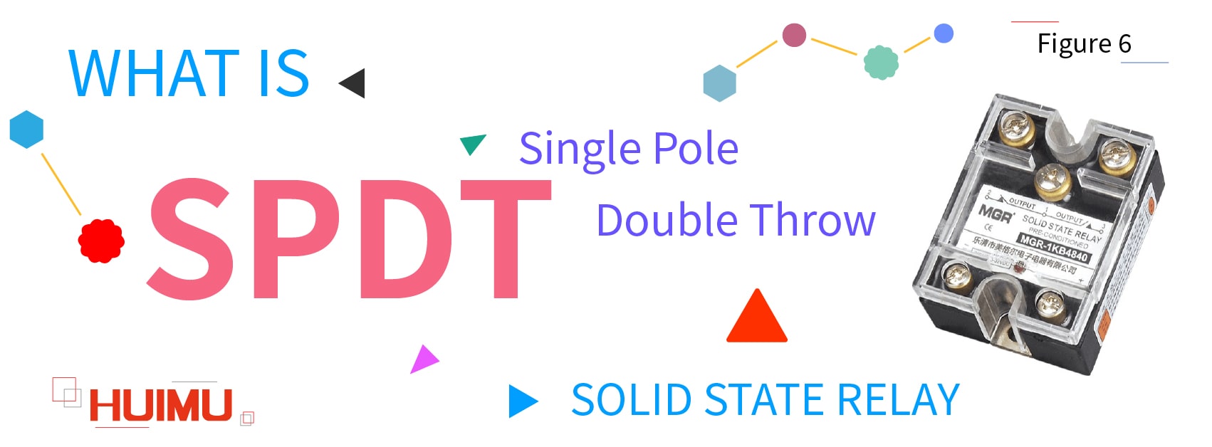
All the switch component (MOSFET, SCR, TRIAC, IGBT, etc.) in the solid state relay only acts as a SPST switch, and there is no single component in the solid state relay that has the SPDT function. Besides, the opto-coupler (with optoelectronic isolation feature) is used in the normal solid state relay as the signal transmission component, so the input control circuit of the SSR switch is electrical insulated to its output circuit. Therefore, if an SPDT solid state relay is required, we can only modify the SPST SSR switch by using a special circuit. And because of the electronic switch components, SPDT solid state relays is more efficient and consumes lower power than SPDT mechanical relays.
The basics of the SPDT SSR switch structure is a little different to the SPDT switch structure:
"Pole" – "Throw (Throw A and Throw B)":
"General-Purpose Push-Pull Outputs (GPout) ①" – "Diodes and Photodiodes";
"Photodiode array ②" – "N-channel enhancement mode MOSFET and N-channel depletion mode MOSFET"
Open: If the pole is disconnected to one throw, the state of this throw is called open state or open.
Close: If the pole is connected to one throw, the state of this throw is called close state or close.
NO (Normally Open): If the throw circuit is disconnected to the pole by default (when the pole is not energized or charged or the voltage level on the pole is zero), this throw circuit will be called the normally open circuit (NO circuit, N/O circuit), and the solid state relay switch will be called normally open SSR switch (NO SSR switch, N/O SSR switch).
NC (Normally Close): If the throw circuit is connected to the pole by default (when the pole is not energized or charged or the voltage level on the pole is zero), this throw circuit will be called the normally closed circuit (NC circuit, N/C circuit), and the solid state relay switch will be called normally closed SSR switch (NC SSR switch, N/C SSR switch).
① Push-Pull Outputs: The push-pull outputs are usually used for two triodes which are controlled by two complementary signals (that is, if one transistor is turned on, the other transistor must be turned off). And the push-pull outputs can output the high voltage level and low voltage level, both of which have the capability to drive the switch components.
② Photodiode array: the stack of photodiodes is used to drive a pair of MOSFETs or an IGBT.
2.1 How does SPDT Solid State Relay work
According to “Pole – Throw”, SPDT solid state relays can be divided into two types: Push-Pull type, and Photodiode-Array type.
1) Push-Pull Type SPDT Solid State Relay
The common circuit diagram of the push-pull SPDT SSR relay as shown below (as shown in Figure 7). The push-pull type SPDT SSR switch consists of two LEDs (D1, D2), and two Photo-TRIACs (TRIAC1, TRIAC2). D1 and TRIAC1 form the CIRCUIT1, and D2 and TRIAC2 form the CIRCUIT2. The push-pull signal (GPout) is generated in the input control terminal of the SPDT SSR, and LOAD1 and LOAD2 is connected to the two output terminals of the SPDT SSR relay.
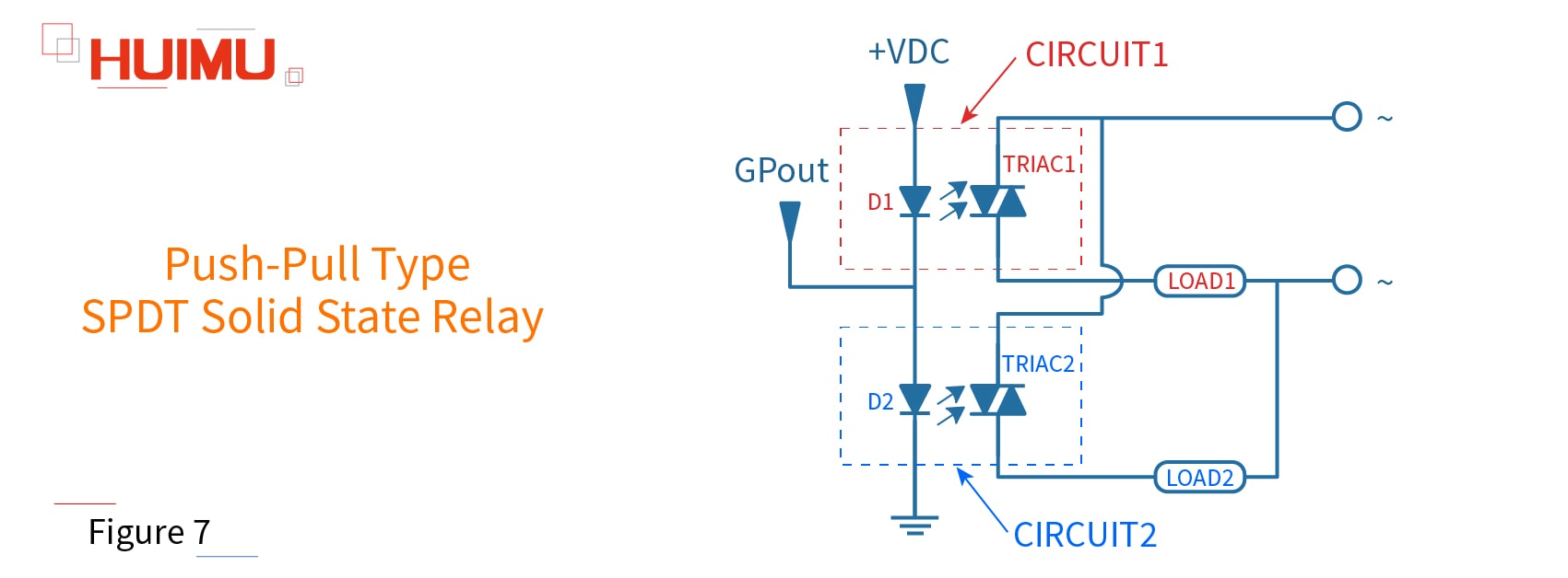
According to the GPout signal, there will be three status of the SPDT solid state relay:
1. When a low voltage level is generated in the input terminal, D2 will be turned off, and D1 will be turned on, and TRIAC1 will conduct, then the CIRCUIT1 will be closed, finally the LOAD1 will be switched on.
2. When a high voltage level is generated in the input terminal, D1 will be turned off, and D2 will be turned on, and TRIAC2 will conduct, then the CIRCUIT2 will be closed, finally the LOAD2 will be switched on.
3. If there is no signal on the input terminal, D1 and D2 will be turned off, and CIRCUIT1 and CIRCUIT2 will not be switched on.
Note: Since the GPout outputs and the operating voltage of LED needs to meet certain limits and requirements, the application of Push-pull type SPDT solid state relay is not very extensive.
2) Photodiode-Array Type SPDT Solid State Relay
Following shows the common circuit diagram of the photodiode-array SPDT SSR relay (as shown in Figure 8), which can work in DC power supply and AC power supply. The photodiode-array type SPDT SSR switch consists of one photodiode-array (D1), and four N-MOSFETs (MOS1 and MOS2 are enhancement mode N-MOSFETs③; MOS3 and MOS4 are depletion mode N-MOSFETs④). MOS1 and MOS2 form the CIRCUIT1, and MOS3 and MOS4 form the CIRCUIT2. There are 5 output terminals, Port1, Port2, Port3, Port4, Port5, and the Port1 is the common terminal. LOAD1 and LOAD2 is connected to the SPDT switch.
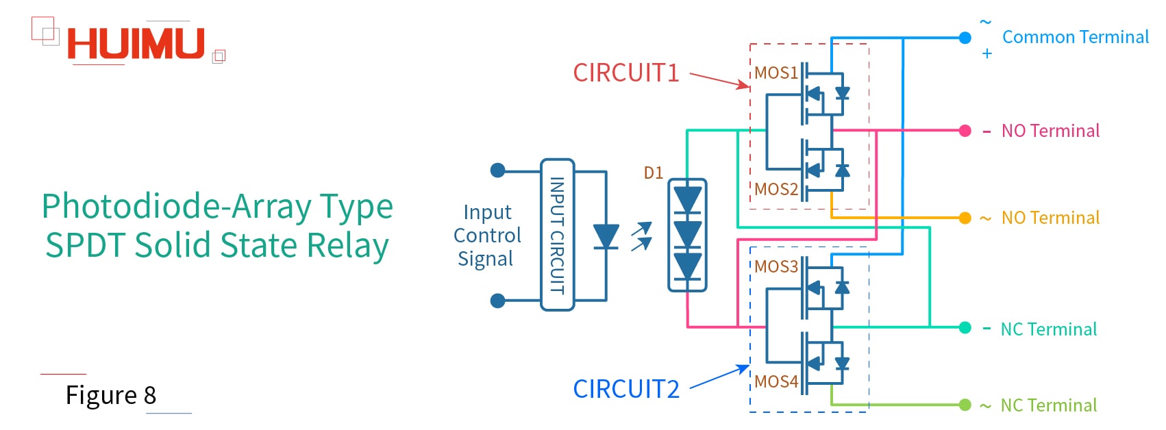
③ The enhancement mode N-channel MOSFET will turn on when Vgs>Vgs(th)⑤, otherwise it will not conduct.
④ The depletion mode N-channel MOSFET will turn on at zero input, and turn off when its Vgs is negative.
⑤ Vgs is the voltage from gate to source; Vgs(th) is the threshold voltage from gate to source.
1. DC Power Supply
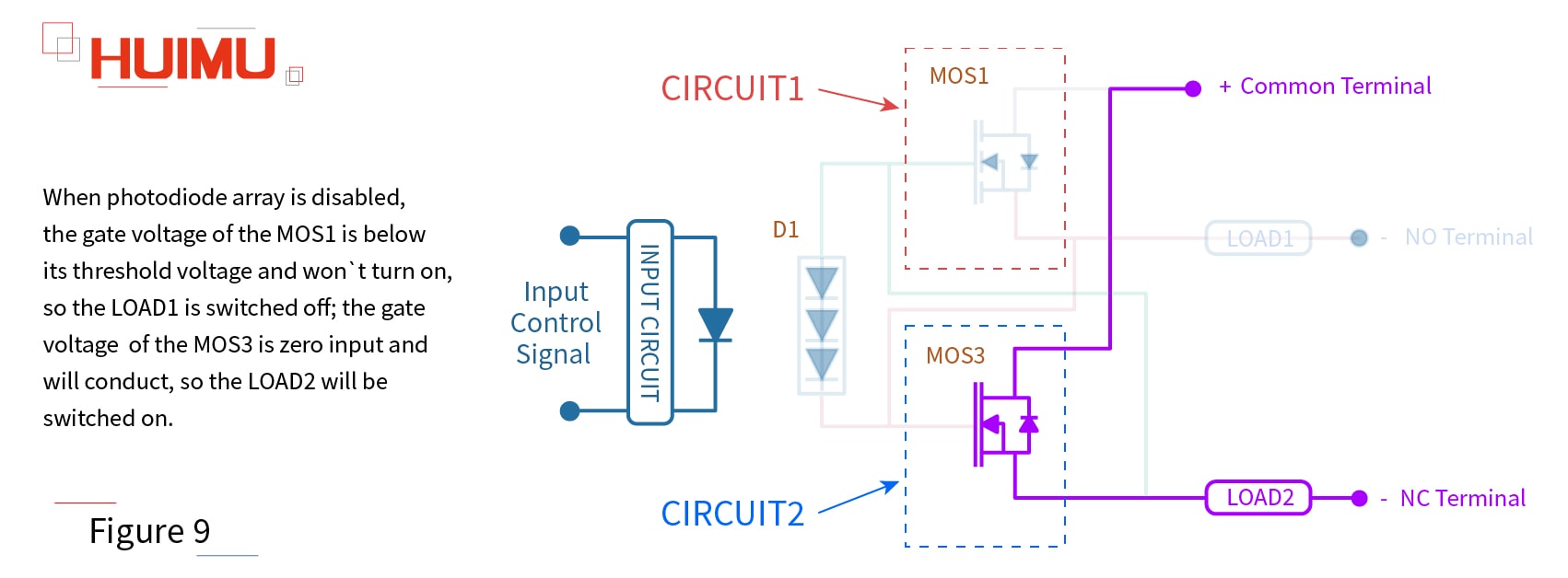
When the photodiode-array SPDT SSR relay is working in a DC power supply, the LOAD1 should be connected to the PORT2, and the LOAD2 should be connected to the PORT4, so the MOS2 and MOS4 will not work.
When photodiode array is disabled, the gate voltage of the MOS1 is below its threshold voltage and won't turn on, so the LOAD1 is switched off; the gate voltage of the MOS3 is zero input and will conduct, so the LOAD2 will be switched on (as shown in Figure 9).
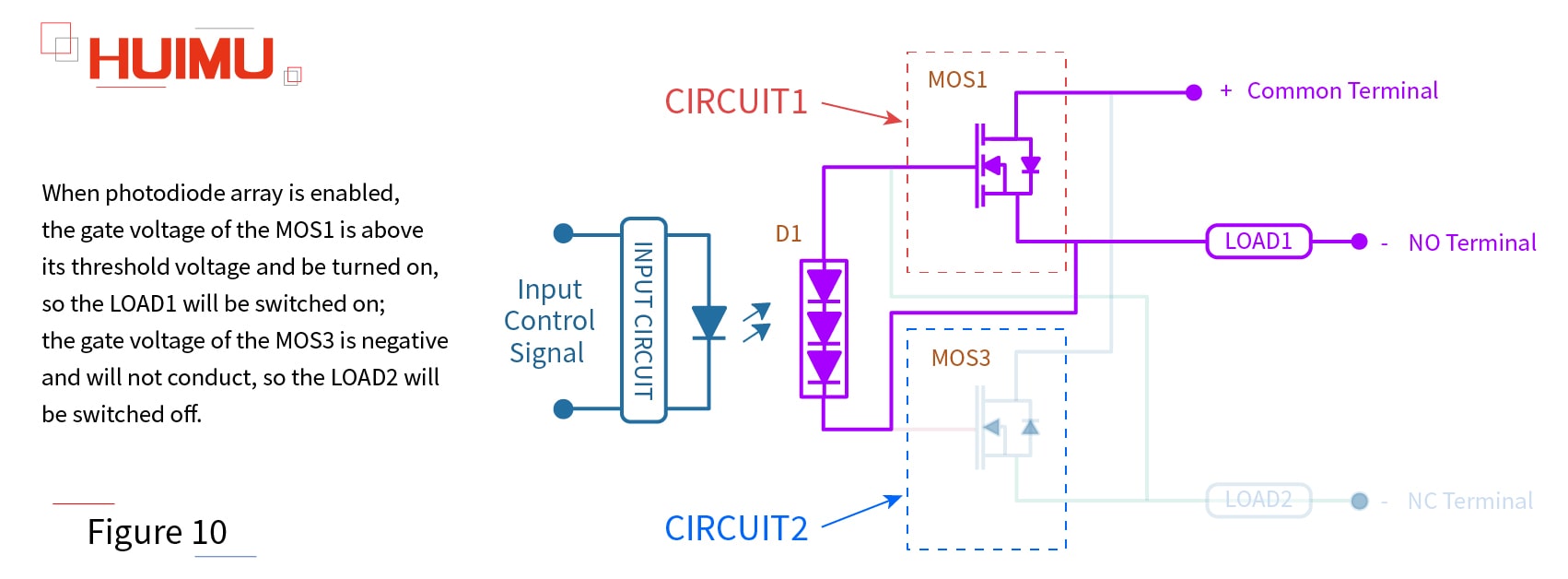
When photodiode array is enabled, the gate voltage of the MOS1 is above its threshold voltage and be turned on, so the LOAD1 will be switched on; the gate voltage of the MOS3 is negative and will not conduct, so the LOAD2 will be switched off (as shown in Figure 10).
2. AC Power Supply
When the photodiode-array SPDT SSR relay is working in an AC power supply, the LOAD1 should be connected to the PORT3, and the LOAD2 should be connected to the PORT5.
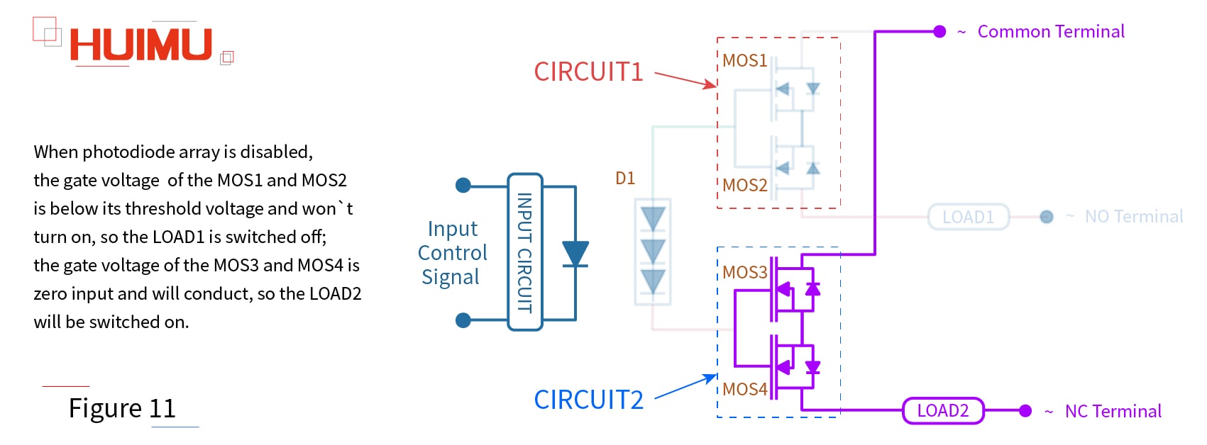
When photodiode array is disabled, the gate voltage of the MOS1 and MOS2 is below its threshold voltage and won't turn on, so the LOAD1 is switched off; the gate voltage of the MOS3 and MOS4 is zero input and will conduct, so the LOAD2 will be switched on (as shown in Figure 11).
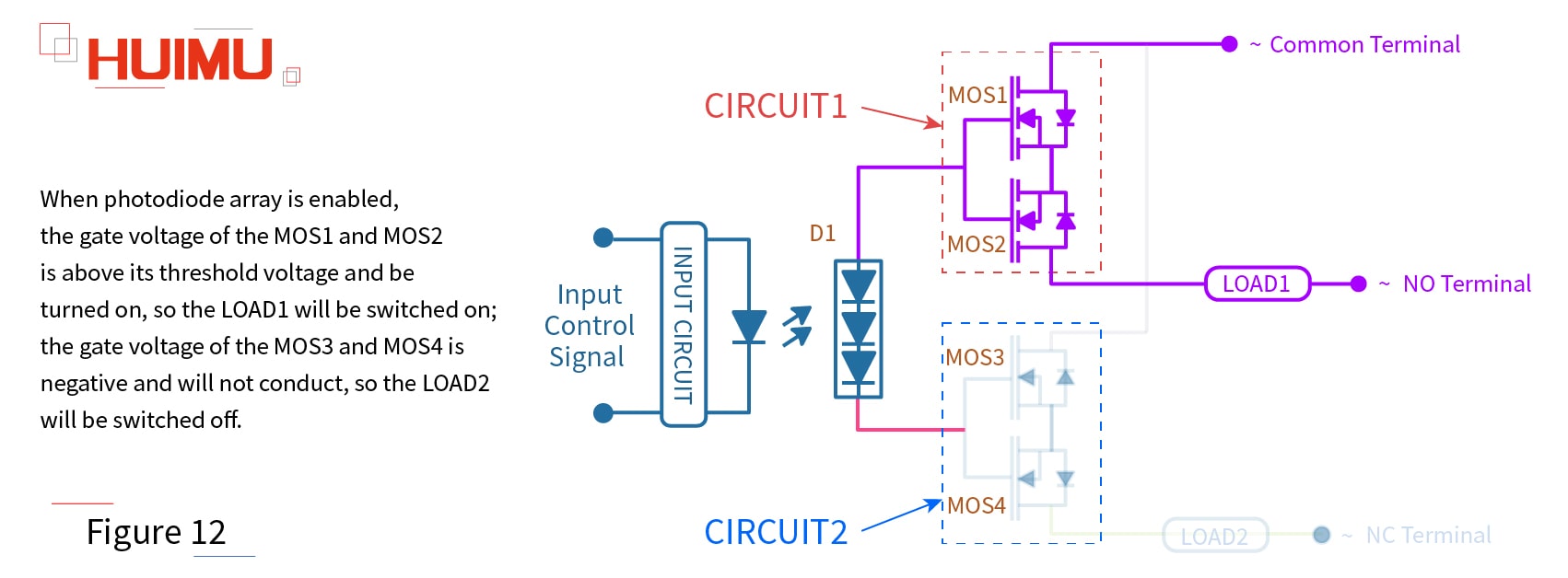
When photodiode array is enabled, the gate voltage of the MOS1 and MOS2 is above its threshold voltage and be turned on, so the LOAD1 will be switched on; the gate voltage of the MOS3 and MOS4 is negative and will not conduct, so the LOAD2 will be switched off (as shown in Figure 12).
Note: Because of the features of N channel enhancement MOSFETs and N channel depletion MOSFETs, this kind of solid state relays are widely used to control the DC load circuit and the AC load circuit.
2.2 What is SPDT solid state relay used for
Solar Battery Charger
SPDT solid state relays are typically used in solar power charger systems (such as portable solar charger) to control the solar cell charging equipment. The working state (charging state and power state) of the solar cells is switched much frequently, so the SPDT mechanical relays cannot meet this requirement, but the SPDT SSRs can.
Soft Starter System
When the electronic/electrical systems (and their subsystems) works normally, the switching frequency of its soft start state and stop state is very high. Therefore, the SPDT make-before-break switch need to be equipped to prevent overvoltage when switching.
Remote Control Device / Radio Transmitter
If the remote control device wants to control multiple objects, it needs to change the transmitted signal; if the communication tower wants to switch the recipient, it needs to change the transmission signal. This kind of equipment require strict operating frequency and operation accuracy, and SPDT solid state relays can meet these requirements in most cases.
Satellite Heater
In the space environment, there are high requirements (weight, anti-interference ability, adaptability, and so on) to every device. The SPDT solid-state relay (with lots of advantages, like small weight, high performance, long service life, low power consumption, low EMR and etc.) meet these requirements, and is much better than the SPDT electromechanical relay (simple structure, but high weight, poor anti-interference ability and cannot adapt to complicated situations due to overweight).
