Showing posts with label basics. Show all posts

Introduction to circuit breakers

Banner of Introduction to circuit breaker

Introduction to circuit breakers

§1. What is a circuit breaker

Electrical Symbol of Circuit Breaker

The circuit breaker is an electrical mechanical device used to break the circuit by separating the contacts when an abnormal current occurs. It is a compact structure composed of mechanical and electrical components such as trip units, an arc extinguishing chamber, Flux converters and so on. In the circuit, the circuit breaker is in the normally closed state, and only the circuit has an abnormal state (such as circuit overload, short circuit, excessive leakage current, ground fault, remote control shutdown, etc.), the opening operation is performed to protect the circuit and the power supply. Although the circuit breaker contains a large number of mechanical actions, it does not switch frequently in the circuit, so its mechanical life is relatively long.

In addition, circuit breakers need to carry large currents and have very strict requirements for reliability and stability. Compared with semiconductor devices with leakage and reverse leakage, circuit breakers generally use mechanical switches.

§2. What are the structures of the circuit breaker

Construction of circuit breaker

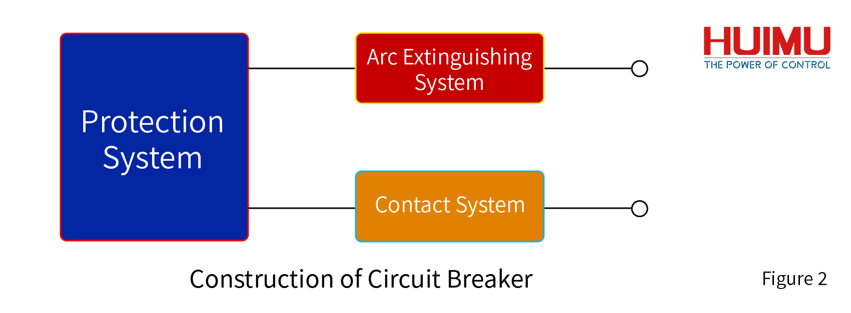
Circuit breakers include mechanical and electrical structures, which can be divided into three systems: contact system, arc extinguishing system, and protection system. The contact system is used to ensure the stable operation of the circuit and is controlled by the protection system to perform the on-off operation of the circuit. The arc extinguishing system is designed to extinguish the arc in order to avoid the arc burning down the electrical components during the breaking operation under the working environment of high current. The protection system can be used to set protection conditions, and the circuit will be opened when the protection conditions are triggered. The cooperation of these three systems allows the circuit breaker to complete the specified circuit protection operation.

2.1 Contact System

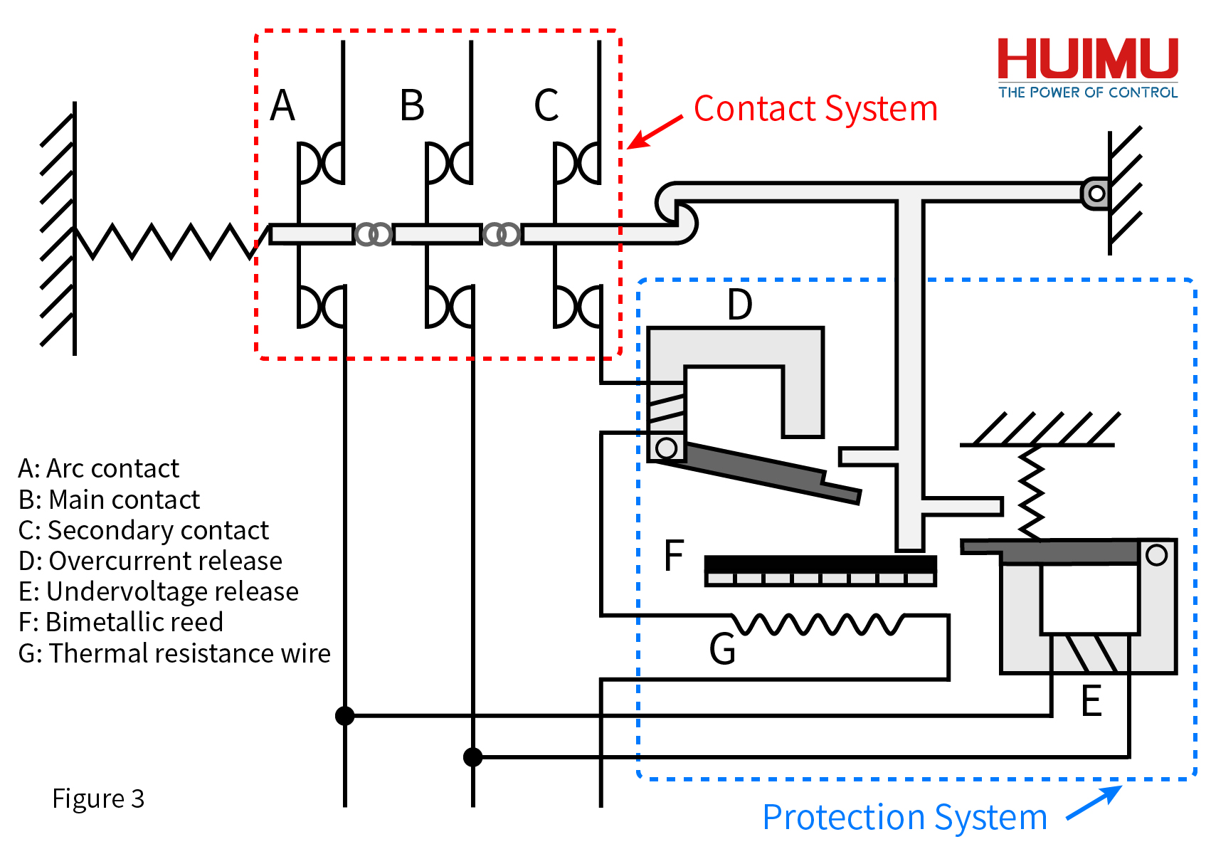
The contact system is directly connected to the external circuit, and its structure generally includes static contacts, moving contacts, auxiliary contacts, connecting rods and other components. When the circuit breaker is closed, the arc contact in the contact system is closed first, then the secondary contact, and finally the main contact is closed; when breaking, the main contact is opened first, followed by the secondary contact, and finally the arc contact is opened. This ensures that the arc will not form on the main contact, so as not to affect the life of the appliance.

Contact type

Auxiliary contacts are contacts mechanically linked with the main circuit opening and closing mechanism of the circuit breaker. They are mainly used to display the opening and closing status of the circuit breaker. Related electrical appliances are controlled or interlocked. For example, output signals to signal lights, relays, etc.

The alarm contact is used to warn in the event of a circuit breaker accident, and this contact will only act after the circuit breaker is tripped and broken. It is mainly used to trip freely when the circuit has an overload, short circuit or undervoltage. The alarm contact is converted from the original normally open position to the closed position, and the indicator light, electric bell, buzzer, etc. in the auxiliary circuit are connected to display or remind the fault trip state of the circuit breaker.

There are three common contact methods: butt contacts, bridge contacts, and plug-in contacts.

How the contact system works

Protecting the main contact and extending its life is the main task of the contact system. The arc will damage the main contact and affect its ability to carry large currents for a long time. Therefore, components such as auxiliary contacts and arc contacts are required to guide the arc to the arc extinguishing chamber.

Structure diagram of circuit breaker

In the contact system, the breaking sequence of the three types of contacts is the main contact, the auxiliary contact, and the arc contact; And the closing sequence is the arc contact, the auxiliary contact, and the main contact. Here mainly introduces the work of the corresponding device of the contact system in the breaking process.

When the breaking operation is performed, the spring first separates the main contact from the corresponding static contact. At this time, the circuit that originally passed through the main contact is redirected to the arc contact through the under-voltage release in the protection system, and the external circuit remains in working condition. Then the secondary contact is broken, and the shunt release or overload release is rerouted to the arc contact through the circuit of the secondary contact. Finally, the arc contact is broken, the external circuit completes the shut-off operation, and the arc is generated on the arc contact and dissipated in the arc extinguishing chamber.

The auxiliary contact can also take on additional functions, such as alarming or sending a signal to the monitoring equipment after a breaking event occurs.

Special cases

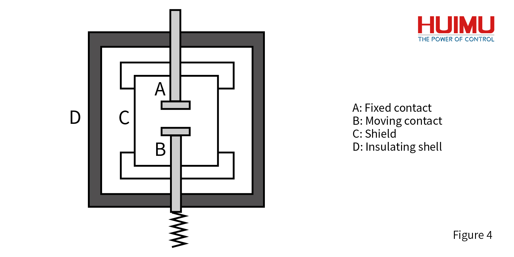
In the vacuum circuit breaker, the contact system has only the main contact, and its structure is shown in the figure below:

vacuum arc extinguishing chamber, the contacts of vacuum circuit breaker

2.2 Arc Extinguishing System

The arc extinguishing system consists of a breaking structure and an arc extinguishing chamber. When the breaking structure performs the circuit breaking operation, the contacts in the contact system are successively broken, and an arc is formed on the arc contact which is finally broken. Then it guide the arc into the arc extinguishing chamber and extinguish the arc.

2.3 Protection System

The protection system includes various trip units and some external control circuits for remote disconnection. The tripping device is mainly composed of electromagnetic coil, magnetic core, tripping mechanism, thermal element, bimetallic sheet and other structures. It is used to realize protection functions in situation such as overload, open circuit, leakage, under-voltage, overvoltage, unbalance, under-frequency, over-frequency, phase sequence.

The following are common releases:

The releases of protection system like Overcurrent release, Overheating release, Under-voltage release, Shunt trip

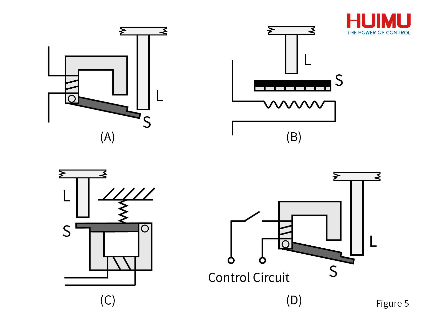
Overcurrent release (short-circuit release): As shown in Figure 5A, it is an overcurrent release, which is a kind of electromagnetic release. At any time during the work of the circuit breaker, if the load current is greater than the short-circuit trip current Im, the overcurrent release of the circuit breaker will trip. First of all, the magnetic field generated by the magnetic flux coil makes the iron buckle produce magnetic force. Then the magnetic force attracts the armature S to overcome the resistance and drive the movable rod L of the free release to move upward. Finally, the free trip unit trips, and the movable contact connected to the rod is driven by the contraction force of the spring to separate from the static contact.

Overheating release (overload release): As shown in Figure 5B, it is an overheating release, which is a thermal magnetic release. In the work of the circuit breaker, if the load current is greater than the overheating trip current Ir for a short period of time, the overheating release will start the tripping operation. When the circuit starts to be overloaded, the heating resistor in the overheating trip unit heats up. In turn, the double-layer metal sheet S is bent upward due to overheating, which drives the movable rod L to move. Then the free release is tripped, and the movable contact connected to the rod is driven by the contraction force of the spring to separate from the static contact. Under certain conditions, the overheating release can also take on short-circuit protection.

Under-voltage release: As shown in Figure 5C, it is an under-voltage release, which is an electromagnetic release. Under normal circumstances, the armature S of the under-voltage release and the magnetic flux ring iron ring are kept closed. When the load voltage is 35% to 70% of the rated voltage Ue, the attraction force generated by the magnetic flux coil is not enough to keep the armature S in a balanced state by the elastic force of the spring acting on it. Therefore, the armature S is driven by the spring force to move the movable rod L of the free mouthpiece upward. Finally, the free release is tripped, and the movable contact connected to the rod is driven by the contraction force of the spring to separate from the static contact. In addition, the circuit breaker can be closed only after the under-voltage release is energized and the load voltage is more than 85% of Ue.

Shunt trip: The shunt trip is shown as 5D in the figure. The control circuit of the shunt release is an external circuit and is divided with the load circuit. The remote control can only be carried out after the switch of the trip unit is closed. When the input voltage of the shunt release is the rated control voltage, the shunt release starts to work. Refer to Short Circuit Release for its working principle.

Electronic trip unit: It can have all the functions of the above trip unit, and can be set in a certain range. The electronic trip unit is a circuit composed of a large number of electronic components, which can monitor the working status of the main circuit, and when an abnormal condition is found, it will push the free trip unit to perform a trip operation.

§3. What are the types of circuit breakers

1.According to the load According to the type of power source, circuit breakers can be divided into DC circuit breakers and AC circuit breakers.

2.According to the arc extinguishing method According to the arc extinguishing method, it can be divided into air circuit breakervacuum circuit breaker, oil circuit breaker, compressed air circuit breaker and Sulfur Hexafluoride Circuit Breaker.

3.According to the switch response speed According to the switch response speed, it can be divided into general type circuit breaker and fast type circuit breaker.

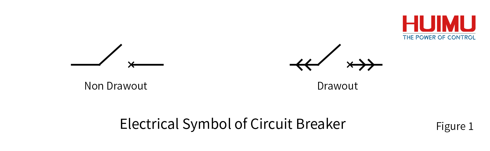
4.According to the installation method According to the installation method, circuit breakers can be divided into fixed circuit breakers, plug-in circuit breakers, withdrawable circuit breakers and embedded circuit breakers.


§4. What are the parameters of the circuit breaker

The main parameters of the circuit breaker are rated voltage and rated current. When the circuit breaker is loaded with other protection functions, there will be corresponding additional parameters according to the required trip unit. These parameters provide important help for choosing a circuit breaker.

1.Input voltage/Input current

The rated voltage (Ue) is the voltage that can maintain the circuit breaker to work uninterruptedly.

The rated current (In) is the maximum current that the circuit breaker can carry under the specified ambient temperature. When the load current exceeds this value, protection devices such as overload protection release and short-circuit protection release will be triggered.

The rated insulation voltage (Ui) is the safe voltage that the circuit breaker itself can carry. When it is higher than this voltage, the circuit breaker may be broken down.

2.Tripping current

Overload relay trip current (long delay Ir; short delay Isd), when the load current value is higher than Ir or Isd for a certain period of time, the overload protection trip will be triggered. The value of Ir is generally 0.4 to 1 times of In in the case of long-time delay interruption, and the value of Isd is generally 3 to 5 times of In in the case of short-time delay. Some circuit breakers can adjust their overload current value.

The short-circuit relay trip current (Im), when the load current value is higher than Im for an instant or a short time, it will trigger the short-circuit protection trip and break the circuit to avoid burning the load. Its value is generally 1.5 to 11 times In or 2 to 10 times Ir.

The ultimate short-circuit breaking capacity (Icu or Icn) is the highest load current value that the short-circuit circuit breaker can operate under certain conditions. When the load current is higher than Icu or Icn, after the operation of breaking the circuit to protect the load is performed, the short circuit breaker will lose its breaking capacity under the rated current.

Operating short-circuit breaking capacity (Ics) refers to the short-circuit current that can be repeatedly closed and broken under certain conditions.

The short-term withstand current (Icw) is the current value that can maintain the circuit closed in a set time of 0.05s, 0.1s, 1s, etc., before the breaking operation is performed when the load current reaches Icw.

3.Power

Power refers to the power when the circuit breaker is operating normally under the closed state.

4.time

The breaking time is also called the opening time, and its value is the sum of the full breaking time and the arcing time. Among them, the full breaking time is the time consumed from the opening operation to the breaking of all the contacts of the contact system, and the arcing time is the time consumed from the arc generation after the contact system is broken to the extinction of all the arcs.

Closing time refers to the time it takes from the execution of the closing operation to the time the contacts are fully closed.

§5. The working principle of the circuit breaker

Structure of circuit breaker

There are many types of circuit breakers. Here we mainly introduce the working principles of air circuit breakers and vacuum circuit breakers. The working principles of other types of circuit breakers are similar.

How the air circuit breaker works

Air Circuit Breaker, also called Air Switch, is a circuit breaker that uses air as the arc extinguishing medium. (As shown in Figure 3)

1.Working process when closed:

① The circuit at the arc contact is closed, and the under-voltage release starts to work. When the voltage at both ends of the release is greater than 0.85 times the rated voltage, the closing operation will be performed ②;

②The circuit of the auxiliary contact is closed, and the overload release starts to work. Only when the load current is less than the overload trip current can the closing operation be performed ③;

③The main contact is closed, and the protection functions of other releases are activated.

2.Working process when breaking:

①The protection function of any trip unit is triggered, and the circuit breaking operation is started;

② The lock hook is tripped, and each contact is disconnected one after another under the traction of the spring;

③The main contact is broken, and the surge generated by the breaking is guided to the circuit where the arc contact is located through the circuit of the under-voltage release;

④The secondary contact is broken, and the surge generated by the breaking is guided to the circuit where the arc contact is located through the circuit of the overload release;

⑤ The arc contact is broken, and the surge current generates an arc after it is broken, which disappears in the arc extinguishing chamber.

How the vacuum circuit breaker works

Vacuum circuit breaker is a circuit breaker that uses vacuum to quickly separate charged ions to block arc extinguishing. The working principle and process of the protection system can be referred to protection system, the main difference from the air circuit breaker is the arc extinguishing system. The vacuum circuit breaker has no arc contacts. When the power is cut off, an arc is directly generated on the main contact and the arc is extinguished in the vacuum interrupter. (As shown in Figure 4)

1.Working process when closed:

①The under-voltage release detects whether the voltage meets the starting conditions. When the conditions are met, it is closed and operation ② is performed.

②The main contact and static contact in the vacuum interrupter are closed, and the external circuit is turned on.

③Other trip units start to work and perform protection tasks.

2.Working process when breaking:

①Any trip unit triggers the protection mechanism to perform the breaking operation.

②The external mechanical device (Breaking Spring) pulls the movable rod where the main contact is located to move downward.

②The main contact and the static contact are disconnected, and the external circuit is disconnected and an arc containing dotted ions is generated at the same time. Charged ions diffuse rapidly in a vacuum environment, and the arc disappears.

§6. What are the applications of circuit breakers

Circuit breakers are often used in equipment that distributes electrical energy to prevent accidents of a single electrical device from affecting other electrical appliances. It usually appears in equipment such as substation boxes and switch cabinets. The following are the main application places.

Household switch cabinet

There are many electrical equipment in modern houses, and the power of all kinds of electrical equipment is different. The traditional use of fuses to protect household appliances and cannot meet people's needs. In addition, the fuse replacement operation is extremely dangerous. Therefore, various air switches are used to protect different power-consuming areas. The air switch is easy to reset and can be switched on and off repeatedly.

Distribution Cabinet

The power distribution cabinet can effectively distribute electric energy, and its internal circuit structure is complicated. In order to ensure the service life and safety of the power distribution cabinet, various circuit breakers are required to perform different protection tasks. Vacuum circuit breakers and multi-oil circuit breakers are often used here to protect corresponding load equipment under high-voltage and high-current conditions. Such as Prefabricated Substation, Outdoor Prefabricated Transformer Substation.

Motor protection

When the motor is working, it will encounter various situations, which will cause the motor to overload, under-voltage, overvoltage and so on. Motor equipment is generally very expensive. Therefore, the corresponding DC and AC circuit breakers are required to protect them to prevent them from burning out when encountering extreme conditions.

Leakage Protection

Many high-power devices will generate extremely dangerous leakage currents on their surfaces or upstream and downstream circuits during operation. Under normal circumstances, a leakage relay is used to continuously neutralize the leakage to ensure the working safety of the equipment. However, some leakage circuit breakers are still needed to preventively protect the extreme leakage current that may directly burn the equipment. Such as Metal-enclosed Ring Main Unit Switchgear, High Voltage Shunt Capacitor Compensation Switchgear


Contact us HUIMULTD

How to wire MGR phase-shift trigger module?


§1. How to wire Solid State Relay Phase-shift Trigger Module

1.1 Single Phase Solid State Relay Phase-shift Trigger Module

SSR-JK Series 

Copyright @ huimultd.com

This single phase solid state relay phase-shift trigger module needs to be equipped with an 18VAC synchronous transformer, a random conduction type solid state relay (or random fire solid state relay), so it is also called a single phase random conduction type solid state relay phase-shift trigger module (or single phase random fire ssr phase trigger module). According to the installation methods, the solid state relay phase-shift trigger module can be divided into PCB mounting type (SSR-JKZK), Panel mounting type (SSR-JKWK). SSR-JKZK is directly mounted on the printed circuit board without heat sink, and cooled by natural cooling; SSR-JKWK is mounted to the metal baseplate or heat sink, and cooled by forced cooling.
● The ① and ② ports are connected to the 18VAC secondary winding of the synchronous transformer to offer the power supply and the synchronous reference for the phase-shift trigger;
● The ③ port is the internal common ground terminal.
● The ④ port is the output terminal.
● The ⑤ port is the internal common ground terminal. If the phase-shift trigger is controlled by the external automatic control circuit, the ⑤ port will be connected to the ground of the external control circuit.
● The ⑥ port is the control terminal. When there is a 0.5V voltage signal inputted to the ⑥ port, a wide pulse (whose phase can be shifted from 180° to 0°) will be produced on the output terminal ④ port (for resistive loads).
● The ⑦ port is the +5V voltage terminal generated inside the module. If the ⑤, ⑥, ⑦ ports are connected to the external potentiometer to apply the manual control method, the ⑦ port acts as the power supply for it; if the control signal is provided by external control circuit to apply the automatic control method, the ⑦ port should be left floating.
● CON must be positive relative to COM, and if the polarity is opposite, the output terminal will be out of control (fully open or fully closed).
● ① and ② ports are connected to the secondary winding of the synchronous transformer, which allows a voltage of 18VAC ± 5VAC and a power of 2W.
● The +5V voltage signal on ⑦ port is only provided for the manual potentiometer (the selected resistance is between 2~10KΩ), not for other uses.
● The pulse level of the ④ port is around 10V, and the maximum output current is 12mA. The phase-shift trigger module can directly match the random conduction type solid state relay produced by our company.
● The AC power grid frequency of the phase-shift trigger module must be 50 Hz.
● The control signal can be divided into automatic control signal (E type: 0~5VDC, F type: 0~10VDC, H type: 1~5VDC, G type: 4~20mA) and manual control signal (potentiometer).

Note:
1) Before installation and use, please confirm whether the specifications (such as input current, input voltage, output current, output voltage and etc.) of the random conduction type solid state relay phase-shift trigger module meet the requirements of the application.
2) MGR-DT Series  regulator module can replace SSR-JKWK series. MGR-DT integrates the synchronous transformer, the phase detection circuit, the phase-shift trigger circuit and the power thyristor output circuit. MGR-DT has a lower overall price and cost of use.
3) If the requirements of your application are low (e.g., no need for complete isolation of input signal and output voltage, only one type of control signal, etc.), then you can use the following instead: Potentiometer type voltage regulator MGR-R Series , Industrial Potentiometer type voltage regulator MGR-HVR Series , voltage signal type voltage regulator MGR-1VD Series , pulse signal type voltage regulator MGR_DV Series .

1.2 Three Phase Solid State Relay Phase-shift Trigger Module

SSR-3JK Series 

Copyright @ huimultd.com

This three phase solid state relay phase-shift trigger module integrates the three phase phase-detection circuit, the phase-shift circuit, the control circuit and the trigger circuit. SSR-3JK series needs to be equipped with an TB-3 synchronous transformer, three random conduction type solid state relays (or random fire solid state relay), so it is also called a three phase random conduction type solid state relay phase-shift trigger module (or three phase random fire ssr phase trigger module).
● The entire circuit can be applied to 380VAC (300~420VAC), 50Hz power grid. The three phase input cables (R, S, T) in the main circuit has no phase sequence requirements, but the input cables must be strict one-to-one correspondence with the output terminals of the solid state relay, TB-3, and SSR-3JK (such as T corresponding to SSR1 and CON1), otherwise the system will not work normally.
● CON must be positive relative to COM, and if the polarity is opposite, the output terminal will be out of control (fully open or fully closed).
● The four COM ports of the SSR-3JK are connected together inside the module to form the weak current "earth ground" (fully isolated with the neutral line "N line" of the synchronous transformer), which will be connected to the DC "earth ground" controlled by the external circuit when choose the automatic control mode.
● The power of the three phase load should be balanced.
● SSR-3JK and TB-3 generate very little heat and do not need to be mounted on a heat sink.
● The control signal can be divided into automatic control signal (E type: 0~5VDC, F type: 0~10VDC, H type: 1~5VDC, G type: 4~20mA) and manual control signal (potentiometer).

Note:
1) Before installation and use, please confirm whether the specifications (such as input current, input voltage, output current, output voltage and etc.) of the three phase solid state relay phase-shift trigger module meet the requirements of the application.
2) MGR-STY Series  regulator module can replace SSR-3JK series. MGR-STY integrates the three phase phase-detection circuit, the phase-shift circuit, the trigger circuit and three sets of reverse-parallel SCR thyristor, MGR-STY has a lower overall price and cost of use.

§2. How to wire Thyristor Phase-shift Trigger Module

2.1 Single Phase Thyristor Phase-shift Trigger Module

SCR-JKK, TRIAC-JKK Series 

This single phase thyristor phase-shift trigger module series needs to be equipped with an 18VAC synchronous transformer, and a power thyristor output circuit. According to the output thyristor type of the power thyristor output circuit, it can be divided into SCR-JKK, TRAIC-JKK. SCR-JKK is used for the SCR power thyristor output circuit; TRAIC-JKK is used for TRAIC power thyristor output.
● The ① and ② ports are connected to the 18VAC secondary winding of the synchronous transformer to offer the power supply and the synchronous reference for the phase-shift trigger
● The ③ port is connected to the trigger gate of the thyristor
● The ④ port is connected to the anode of the SCR thyristor or the main electrode T1 of the TRIAC thyristor
● The ⑤ port is the internal common ground terminal. If the phase-shift trigger is controlled by the external automatic control circuit, the ⑤ port will be connected to the ground of the external control circuit
● The ⑥ port is the control terminal. When there is a 0.5V voltage signal inputted to the ⑥ port, the thyristor on the ③ and ④ ports will be triggered in the phase-shift range of 180°~0°
● The ⑦ port is the +5V voltage terminal generated inside the module. If the ⑤, ⑥, ⑦ ports are connected to the external potentiometer to apply the manual control method, the ⑦ port acts as the power supply for it; if the control signal is provided by external control circuit to apply the automatic control method, the ⑦ port should be left floating.
● CON must be positive relative to COM, and if the polarity is opposite, the output terminal will be out of control (fully open or fully closed).
● ① and ② ports are connected to the secondary winding of the synchronous transformer, which allows a voltage of 18VAC ± 5VAC and a power of 2W.
● The +5V voltage signal on ⑦ port is only provided for the manual potentiometer (the selected resistance is between 2~10KΩ), not for other uses. Note: The G type (4~20mA as control signal) cannot be manually adjusted by the potentiometer, so the +5V port is useless for the G type.
● The phase-shift trigger module can trigger thyristors within 1000A current (please pay attention to the connection method of the trigger terminal).
● In the RC circuit, the resistance is generally 15~30Ω, 3W or more; the capacitance is 0.1~0.47μF, 250VAC/400VAC or above; and the positions of R and C are not interchangeable.
● One end of C should be connected to the cathode of the single phase thyristor or the main electrode T2 of the TRIAC)
● The control signal can be divided into automatic control signal (E type: 0~5VDC, F type: 0~10VDC, H type: 1~5VDC, G type: 4~20mA) and manual control signal (potentiometer).

Note:
1) Before installation and use, please confirm whether the specifications (such as input current, input voltage, output current, output voltage and etc.) of the single phase thyristor phase-shift trigger module meet the requirements of the application.
2) MGR-DT Series  half-wave type regulator module(one SCR as the output component)can replace SCR-JKK series. MGR-DT series ordinary type regulator module(one TRIAC as the output component)can replace TRAIC-JKK series. MGR-DT integrates the synchronous transformer, the phase detection circuit, the phase-shift trigger circuit and the thyristor output circuit. MGR-DT has a lower overall price and cost of use.

Copyright @ huimultd.com

Figure 2.1A, SCR-JKK circuit wiring diagram

Copyright @ huimultd.com

Figure 2.1B, SCR-JKK circuit wiring diagram (static dv/dt improved version)

Copyright @ huimultd.com

Figure 2.1C, TRAIC-JKK circuit wiring diagram 1

Copyright @ huimultd.com

Figure 2.1D, TRAIC-JKK circuit wiring diagram 1 (static dv/dt improved version)

Copyright @ huimultd.com

Figure 2.1E, TRAIC-JKK circuit wiring diagram 2

2.2 Single Phase Dual Channel Thyristor Phase-shift Trigger Module

SCR-JKK/2 Series 

The principle of the single phase dual channel thyristor phase-shift trigger module (SCR-JKK/2) is: On the basis of SCR-JKK, add one thyristor trigger signal of the negative half period to achieve the simultaneous phase-shift adjustment of the positive and negative half periods of two single phase thyristors in the single phase circuit. Except for it, the parameters and performance of SCR-JKK/2 are the same as SCR-JKK.
● SPECIAL ATTENTION: TRIAC-JKK, SCR-JKK and SCR-JKK/2 these three types modules adopt strong electric trigger mode, so when the module cannot be triggered to conduction due to the damage of the thyristor gate, if there still remains voltage on the trigger module, the current of the power grid will enter from the A port and then pass through the G port to the load, and the vast majority of the power grid voltage will be applied to both ends of A and G, after that there will be huge heat generated caused by the high voltage and current, which will burn and damage internal components connected to the both ends of A and G in few seconds. It is the main deficiency of these three kinds of module s that the trigger module will be damaged caused by the damage of the gate of the thyristor.
● IMPROVEMENT DESCRIPTIONS: For these phase-shift trigger module series, in order to improve the static dv/dt of the voltage regulation system (consisting of the phase-shift trigger module, the thyristor and the synchronous transformer) and also prevent the voltage regulation system from being damaged by the transient voltage (once switched and powered on), the load circuit should be changed the following static dv/dt improved version: The A port of the phase-shift trigger module should be connected to the midpoint of the corresponding RC snubber loop, and the connection method of R and C must be as shown in the figure (that is, one end of R should be connected to the anode of the single-phase thyristor or the main electrode T1 of the TRIAC, and one end of C should be connected to the cathode of the single phase thyristor or the main electrode T2 of the TRIAC), and the positions of R and C cannot be exchanged. The resistance of the RC circuit is generally 15~30Ω, 3W or more, and the capacitance is 0.1~0.47μf, 250VAC/400VAC or more.

Note:
1) Before installation and use, please confirm whether the specifications (such as input current, input voltage, output current, output voltage and etc.) of the single phase dual channel thyristor phase-shift trigger module meet the requirements of the application.
2) If SCR-JKK/2 is used for voltage regulator circuit, MGR-DT Series  can replace SCR-JKK/2 series. MGR-DT integrates the synchronous transformer, the phase detection circuit, the phase-shift trigger circuit and the thyristor output circuit. MGR-DT has a lower overall price and cost of use.
3) If SCR-JKK/2 is used for voltage regulation rectifier circuit, MGR-DQZ Series  can replace SCR-JKK/2 series. integrates the fully-controlled bridge rectifier (consisting of four SCR thyristors), the phase-shift circuit and the trigger circuit. MGR -DQZ has a lower overall price and cost of use.

Copyright @ huimultd.com

Figure 2.2A, SCR-JKK/2 circuit wiring diagram 1

Copyright @ huimultd.com

Figure 2.2B, SCR-JKK/2 circuit wiring diagram 2

Copyright @ huimultd.com

Figure 2.2C, SCR-JKK/2 circuit wiring diagram 3

Copyright @ huimultd.com

Figure 2.2D, SCR-JKK/2 circuit wiring diagram 1 (static dv/dt improved version)

Copyright @ huimultd.com

Figure 2.2E, SCR-JKK/2 circuit wiring diagram 2 (static dv/dt improved version)

2.3 Three Phase Thyristor Phase-shift Trigger Module

SX-JK Series 

The three phase thyristor phase-shift trigger module integrates the three phase phase-detection circuit, the phase-shift circuit, the control circuit and the trigger circuit. This single phase thyristor phase-shift trigger module series needs to be equipped with an TB-3A/TB-3Z synchronous transformer, and a three phase power thyristor output circuit. SX-JK can be divided into four series: three phase SCR type phase-shift trigger module (SX-JKA), three phase TRIAC type phase-shift trigger module (SX-JKT), three phase fully-controlled rectification phase-shift trigger module (SX-JKZ) and three phase half-controlled rectification phase-shift trigger module (SX-JKB).
● The three phase AC voltage regulation circuit has no phase sequence requirements, but the three phase input cables (R, S, T) in the three phase rectifier circuit has phase sequence requirements. Besides, the input cables and the thyristor (such as R corresponding to the anode of KP1 and the cathode of KP4), the synchronous transformer module and the three phase trigger must be strictly one-to-one correspondence, otherwise the system will not work normally.
● The trigger terminals of the three phase trigger (such as A1, G1, ..., A6, G6) adopt the strong current trigger mode, which can trigger any SCR thyristor within 1000A current. The connection method of the so-called strong current trigger mode is to connect A1 and G1 (corresponding to the anode and gate of KP1) instead of the usual cathode and gate.
● CON must be positive relative to COM, and if the polarity is opposite, the output terminal will be out of control (fully open or fully closed).
● The power of the three phase load should be balanced.
● In the RC circuit, the resistance is generally 15~30Ω, 3W or more; the capacitance is 0.1~0.47μF, 250VAC/400VAC or above; and the positions of R and C are not interchangeable.
● One end of C should be connected to the cathode of the single phase thyristor or the main electrode T2 of the TRIAC)
● The control signal can be divided into automatic control signal (E type: 0~5VDC, F type: 0~10VDC, H type: 1~5VDC, G type: 4~20mA) and manual control signal (potentiometer).

Note:
1) Before installation and use, please confirm whether the specifications (such as input current, input voltage, output current, output voltage and etc.) of the three phase thyristor phase-shift trigger module meet the requirements of the application.
2) MGR-STY Series  can replace SX-JKA and SX-JKT series. MGR- STY integrates the three phase phase-detection circuit, the phase-shift circuit, the trigger circuit and three sets of reverse-parallel SCR thyristors. MGR-STY has a lower overall price and cost of use.

Copyright @ huimultd.com

Figure 2.3A, SX-JKA circuit wiring diagram

Copyright @ huimultd.com

Figure 2.3B, SX-JKA circuit wiring diagram (static dv/dt improved version)

Copyright @ huimultd.com

Figure 2.3C, SX-JKT circuit wiring diagram

Copyright @ huimultd.com

Figure 2.3D, SX-JKZ circuit wiring diagram

Copyright @ huimultd.com

Figure 2.3E, SX-JKZ circuit wiring diagram (static dv/dt improved version)

Copyright @ huimultd.com

Figure 2.3F, SX-JKB circuit wiring diagram

Copyright @ huimultd.com

How to wire MGR multi-channel solid state relay?


§1. How to wire SPDT Solid State Relay

1.1 SPDT DC to AC Solid State Relay

MGR-1KB Series 

Copyright @ huimultd.com

This SPDT (single pole double throw) solid state relay has five terminals—two input terminals, two output terminals, and one output common terminal. Two input terminals are connected to the DC control signal device. Two output terminals are connected to two different single-phase AC load circuits. The output common terminal is the common terminal of the two AC load circuits. You can seamlessly switch the output circuit from the Load1 to the Load2 (or from the Load2 to Load1) by the control signal. The LED will show the working status of this solid state relay.

Note: Before installation and use, please confirm whether the specifications (such as input current, input voltage, output current, output voltage and etc.) of the spdt solid state relay meet the requirements of the application.

1.2 SPDT AC to AC Solid State Relay

MGR-1AKB Series 

Copyright @ huimultd.com

This SPDT (single pole double throw) solid state relay has five terminals—two input terminals, two output terminals, and one output common terminal. Two input terminals are connected to the AC control signal device. Two output terminals are connected to two different single-phase AC load circuits. The output common terminal is the common terminal of the two AC load circuits. You can seamlessly switch the output circuit from the Load1 to the Load2 (or from the Load2 to Load1) by the control signal. The LED will show the working status of this solid state relay.

Note: Before installation and use, please confirm whether the specifications (such as input current, input voltage, output current, output voltage and etc.) of the spdt solid state relay meet the requirements of the application.

§2. How to wire Dual Channel Solid State Relay

2.1 Plug-in Installation Type

MGR-1D_2H Series 

Copyright @ huimultd.com

The dual-channel DC to AC solid state relay has eight terminals, or two sets of I/O (input and output) terminals—two couples (four) input terminals, and two couples (four) output terminals. The terminals of this dual-channel solid state relay are plug-in installed, which can be insert connected to the outside circuit through plug-in wiring cold-press terminals. Each set of I/O terminals of the solid state relay is connected to the different input device, output load and power supply. And the two I/O circuits are independent of each other. The LED will show the working status of this solid state relay. This solid state relay can realize the functions of two solid state relays, so it can be used in equipment with strict requirements on installation space.

Note: Before installation and use, please confirm whether the specifications (such as input current, input voltage, output current, output voltage and etc.) of the dual channel solid state relay meet the requirements of the application.

2.2 Lead Installation Type

MGR-1D_2T Series 

Copyright @ huimultd.com

The dual-channel DC to AC solid state relay has eight terminals, or two sets of I/O (input and output) terminals—two couples (four) input terminals, and two couples (four) output terminals. The terminals of this dual-channel solid state relay are lead installed, which can be screw connected to the outside circuit through lead or Y-type wiring cold-press terminals. Each set of I/O terminals of the solid state relay is connected to the different input device, output load and power supply. And the two I/O circuits are independent of each other. The LED will show the working status of this solid state relay. This solid state relay can realize the functions of two solid state relays, so it can be used in equipment with strict requirements on installation space.

Note: Before installation and use, please confirm whether the specifications (such as input current, input voltage, output current, output voltage and etc.) of the dual channel solid state relay meet the requirements of the application.

§3. How to wire Five Channel Solid State Relay

3.1 Five Channel DC to DC Solid State Relay

ST5 Series 

Copyright @ huimultd.com

The five-channel solid state relay has twelve terminals—5 sets of I/O (input and output) terminals, and two common terminals. The terminals of this dual-channel solid state relay are screw installed. Each set of input and output terminals of the solid state relay is connected to the different input device and load. And each I/O circuit is independent of each other. The five input terminals are connected to the different DC control devices. The five output terminals are connected to the same DC power supply. The LED will show the working status of this solid state relay. This solid state relay can realize the functions of five solid state relays, so it can be used in equipment with strict requirements on installation space.

Note: Before installation and use, please confirm whether the specifications (such as input current, input voltage, output current, output voltage and etc.) of the five channel solid state relay meet the requirements of the application.

3.2 Five Channel DC to AC Solid State Relay

PN5 Series 

Copyright @ huimultd.com

The five-channel solid state relay has twelve terminals—5 sets of I/O (input and output) terminals, and two common terminals. The terminals of this dual-channel solid state relay are screw installed. Each set of input and output terminals of the solid state relay is connected to the different input device and load. And each I/O circuit is independent of each other. The five input terminals are connected to the different DC control devices. The five output terminals are connected to the same AC power supply. The LED will show the working status of this solid state relay. This solid state relay can realize the functions of five solid state relays, so it can be used in equipment with strict requirements on installation space.

Note: Before installation and use, please confirm whether the specifications (such as input current, input voltage, output current, output voltage and etc.) of the five channel solid state relay meet the requirements of the application.

Copyright @ huimultd.com

MGR-AH_3 Series Panel Mount Solid State Relay

  MGR-AH_3 Series Panel Mount Solid State Relay [All the information on this website is for reference only, and the actual product and the a...