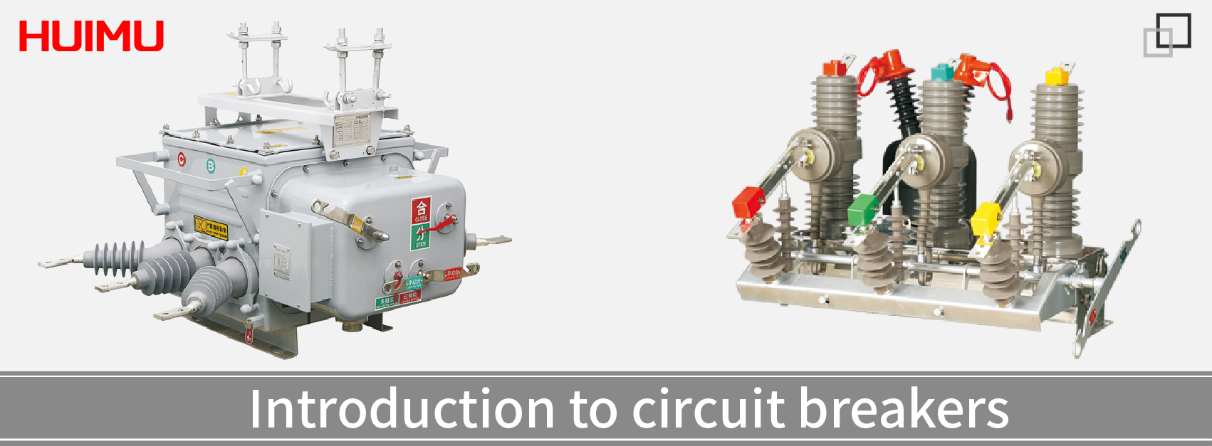
Introduction to circuit breakers
§1. What is a circuit breaker

The circuit breaker is an electrical mechanical device used to break the circuit by separating the contacts when an abnormal current occurs. It is a compact structure composed of mechanical and electrical components such as trip units, an arc extinguishing chamber, Flux converters and so on. In the circuit, the circuit breaker is in the normally closed state, and only the circuit has an abnormal state (such as circuit overload, short circuit, excessive leakage current, ground fault, remote control shutdown, etc.), the opening operation is performed to protect the circuit and the power supply. Although the circuit breaker contains a large number of mechanical actions, it does not switch frequently in the circuit, so its mechanical life is relatively long.
In addition, circuit breakers need to carry large currents and have very strict requirements for reliability and stability. Compared with semiconductor devices with leakage and reverse leakage, circuit breakers generally use mechanical switches.
§2. What are the structures of the circuit breaker
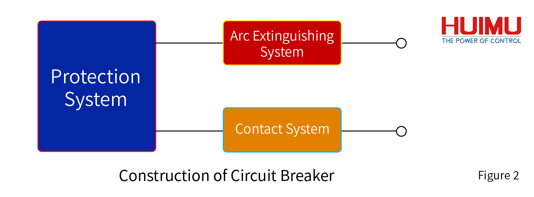
Circuit breakers include mechanical and electrical structures, which can be divided into three systems: contact system, arc extinguishing system, and protection system. The contact system is used to ensure the stable operation of the circuit and is controlled by the protection system to perform the on-off operation of the circuit. The arc extinguishing system is designed to extinguish the arc in order to avoid the arc burning down the electrical components during the breaking operation under the working environment of high current. The protection system can be used to set protection conditions, and the circuit will be opened when the protection conditions are triggered. The cooperation of these three systems allows the circuit breaker to complete the specified circuit protection operation.
2.1 Contact System
The contact system is directly connected to the external circuit, and its structure generally includes static contacts, moving contacts, auxiliary contacts, connecting rods and other components. When the circuit breaker is closed, the arc contact in the contact system is closed first, then the secondary contact, and finally the main contact is closed; when breaking, the main contact is opened first, followed by the secondary contact, and finally the arc contact is opened. This ensures that the arc will not form on the main contact, so as not to affect the life of the appliance.
Contact type
Auxiliary contacts are contacts mechanically linked with the main circuit opening and closing mechanism of the circuit breaker. They are mainly used to display the opening and closing status of the circuit breaker. Related electrical appliances are controlled or interlocked. For example, output signals to signal lights, relays, etc.
The alarm contact is used to warn in the event of a circuit breaker accident, and this contact will only act after the circuit breaker is tripped and broken. It is mainly used to trip freely when the circuit has an overload, short circuit or undervoltage. The alarm contact is converted from the original normally open position to the closed position, and the indicator light, electric bell, buzzer, etc. in the auxiliary circuit are connected to display or remind the fault trip state of the circuit breaker.
There are three common contact methods: butt contacts, bridge contacts, and plug-in contacts.
How the contact system works
Protecting the main contact and extending its life is the main task of the contact system. The arc will damage the main contact and affect its ability to carry large currents for a long time. Therefore, components such as auxiliary contacts and arc contacts are required to guide the arc to the arc extinguishing chamber.
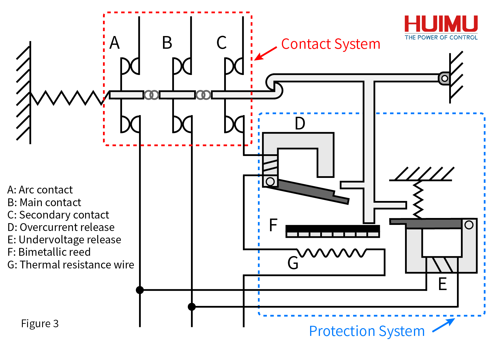
In the contact system, the breaking sequence of the three types of contacts is the main contact, the auxiliary contact, and the arc contact; And the closing sequence is the arc contact, the auxiliary contact, and the main contact. Here mainly introduces the work of the corresponding device of the contact system in the breaking process.
When the breaking operation is performed, the spring first separates the main contact from the corresponding static contact. At this time, the circuit that originally passed through the main contact is redirected to the arc contact through the under-voltage release in the protection system, and the external circuit remains in working condition. Then the secondary contact is broken, and the shunt release or overload release is rerouted to the arc contact through the circuit of the secondary contact. Finally, the arc contact is broken, the external circuit completes the shut-off operation, and the arc is generated on the arc contact and dissipated in the arc extinguishing chamber.
The auxiliary contact can also take on additional functions, such as alarming or sending a signal to the monitoring equipment after a breaking event occurs.
Special cases
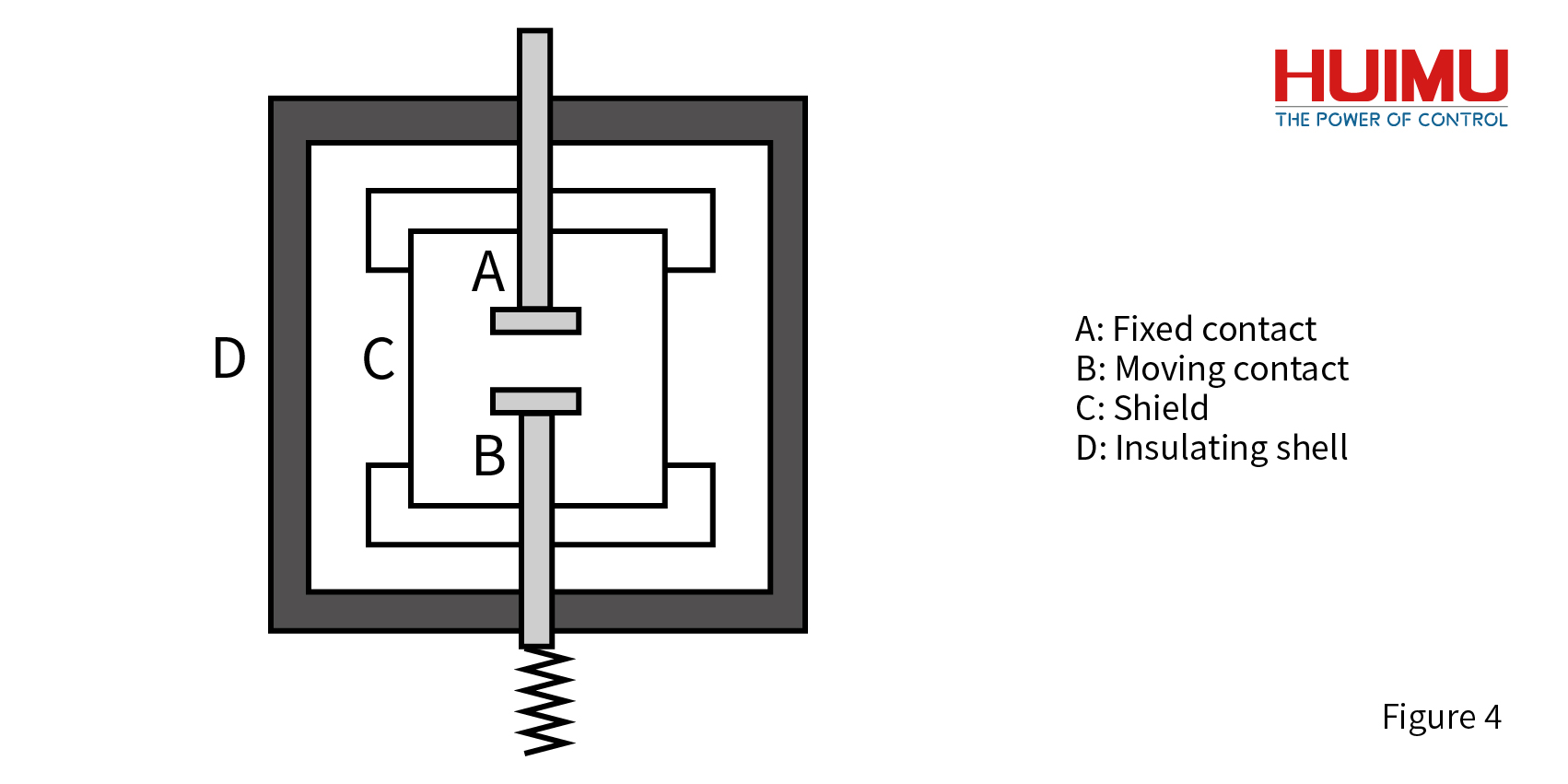
In the vacuum circuit breaker, the contact system has only the main contact, and its structure is shown in the figure below:
2.2 Arc Extinguishing System
The arc extinguishing system consists of a breaking structure and an arc extinguishing chamber. When the breaking structure performs the circuit breaking operation, the contacts in the contact system are successively broken, and an arc is formed on the arc contact which is finally broken. Then it guide the arc into the arc extinguishing chamber and extinguish the arc.
2.3 Protection System
The protection system includes various trip units and some external control circuits for remote disconnection. The tripping device is mainly composed of electromagnetic coil, magnetic core, tripping mechanism, thermal element, bimetallic sheet and other structures. It is used to realize protection functions in situation such as overload, open circuit, leakage, under-voltage, overvoltage, unbalance, under-frequency, over-frequency, phase sequence.
The following are common releases:
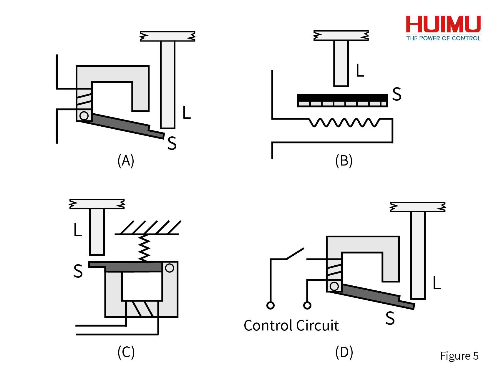
Overcurrent release (short-circuit release): As shown in Figure 5A, it is an overcurrent release, which is a kind of electromagnetic release. At any time during the work of the circuit breaker, if the load current is greater than the short-circuit trip current Im, the overcurrent release of the circuit breaker will trip. First of all, the magnetic field generated by the magnetic flux coil makes the iron buckle produce magnetic force. Then the magnetic force attracts the armature S to overcome the resistance and drive the movable rod L of the free release to move upward. Finally, the free trip unit trips, and the movable contact connected to the rod is driven by the contraction force of the spring to separate from the static contact.
Overheating release (overload release): As shown in Figure 5B, it is an overheating release, which is a thermal magnetic release. In the work of the circuit breaker, if the load current is greater than the overheating trip current Ir for a short period of time, the overheating release will start the tripping operation. When the circuit starts to be overloaded, the heating resistor in the overheating trip unit heats up. In turn, the double-layer metal sheet S is bent upward due to overheating, which drives the movable rod L to move. Then the free release is tripped, and the movable contact connected to the rod is driven by the contraction force of the spring to separate from the static contact. Under certain conditions, the overheating release can also take on short-circuit protection.
Under-voltage release: As shown in Figure 5C, it is an under-voltage release, which is an electromagnetic release. Under normal circumstances, the armature S of the under-voltage release and the magnetic flux ring iron ring are kept closed. When the load voltage is 35% to 70% of the rated voltage Ue, the attraction force generated by the magnetic flux coil is not enough to keep the armature S in a balanced state by the elastic force of the spring acting on it. Therefore, the armature S is driven by the spring force to move the movable rod L of the free mouthpiece upward. Finally, the free release is tripped, and the movable contact connected to the rod is driven by the contraction force of the spring to separate from the static contact. In addition, the circuit breaker can be closed only after the under-voltage release is energized and the load voltage is more than 85% of Ue.
Shunt trip: The shunt trip is shown as 5D in the figure. The control circuit of the shunt release is an external circuit and is divided with the load circuit. The remote control can only be carried out after the switch of the trip unit is closed. When the input voltage of the shunt release is the rated control voltage, the shunt release starts to work. Refer to Short Circuit Release for its working principle.
Electronic trip unit: It can have all the functions of the above trip unit, and can be set in a certain range. The electronic trip unit is a circuit composed of a large number of electronic components, which can monitor the working status of the main circuit, and when an abnormal condition is found, it will push the free trip unit to perform a trip operation.
§3. What are the types of circuit breakers
1.According to the load According to the type of power source, circuit breakers can be divided into DC circuit breakers and AC circuit breakers.
2.According to the arc extinguishing method According to the arc extinguishing method, it can be divided into air circuit breaker, vacuum circuit breaker, oil circuit breaker, compressed air circuit breaker and Sulfur Hexafluoride Circuit Breaker.
3.According to the switch response speed According to the switch response speed, it can be divided into general type circuit breaker and fast type circuit breaker.
4.According to the installation method According to the installation method, circuit breakers can be divided into fixed circuit breakers, plug-in circuit breakers, withdrawable circuit breakers and embedded circuit breakers.
§4. What are the parameters of the circuit breaker
The main parameters of the circuit breaker are rated voltage and rated current. When the circuit breaker is loaded with other protection functions, there will be corresponding additional parameters according to the required trip unit. These parameters provide important help for choosing a circuit breaker.
1.Input voltage/Input current
The rated voltage (Ue) is the voltage that can maintain the circuit breaker to work uninterruptedly.
The rated current (In) is the maximum current that the circuit breaker can carry under the specified ambient temperature. When the load current exceeds this value, protection devices such as overload protection release and short-circuit protection release will be triggered.
The rated insulation voltage (Ui) is the safe voltage that the circuit breaker itself can carry. When it is higher than this voltage, the circuit breaker may be broken down.
2.Tripping current
Overload relay trip current (long delay Ir; short delay Isd), when the load current value is higher than Ir or Isd for a certain period of time, the overload protection trip will be triggered. The value of Ir is generally 0.4 to 1 times of In in the case of long-time delay interruption, and the value of Isd is generally 3 to 5 times of In in the case of short-time delay. Some circuit breakers can adjust their overload current value.
The short-circuit relay trip current (Im), when the load current value is higher than Im for an instant or a short time, it will trigger the short-circuit protection trip and break the circuit to avoid burning the load. Its value is generally 1.5 to 11 times In or 2 to 10 times Ir.
The ultimate short-circuit breaking capacity (Icu or Icn) is the highest load current value that the short-circuit circuit breaker can operate under certain conditions. When the load current is higher than Icu or Icn, after the operation of breaking the circuit to protect the load is performed, the short circuit breaker will lose its breaking capacity under the rated current.
Operating short-circuit breaking capacity (Ics) refers to the short-circuit current that can be repeatedly closed and broken under certain conditions.
The short-term withstand current (Icw) is the current value that can maintain the circuit closed in a set time of 0.05s, 0.1s, 1s, etc., before the breaking operation is performed when the load current reaches Icw.
3.Power
Power refers to the power when the circuit breaker is operating normally under the closed state.
4.time
The breaking time is also called the opening time, and its value is the sum of the full breaking time and the arcing time. Among them, the full breaking time is the time consumed from the opening operation to the breaking of all the contacts of the contact system, and the arcing time is the time consumed from the arc generation after the contact system is broken to the extinction of all the arcs.
Closing time refers to the time it takes from the execution of the closing operation to the time the contacts are fully closed.
§5. The working principle of the circuit breaker
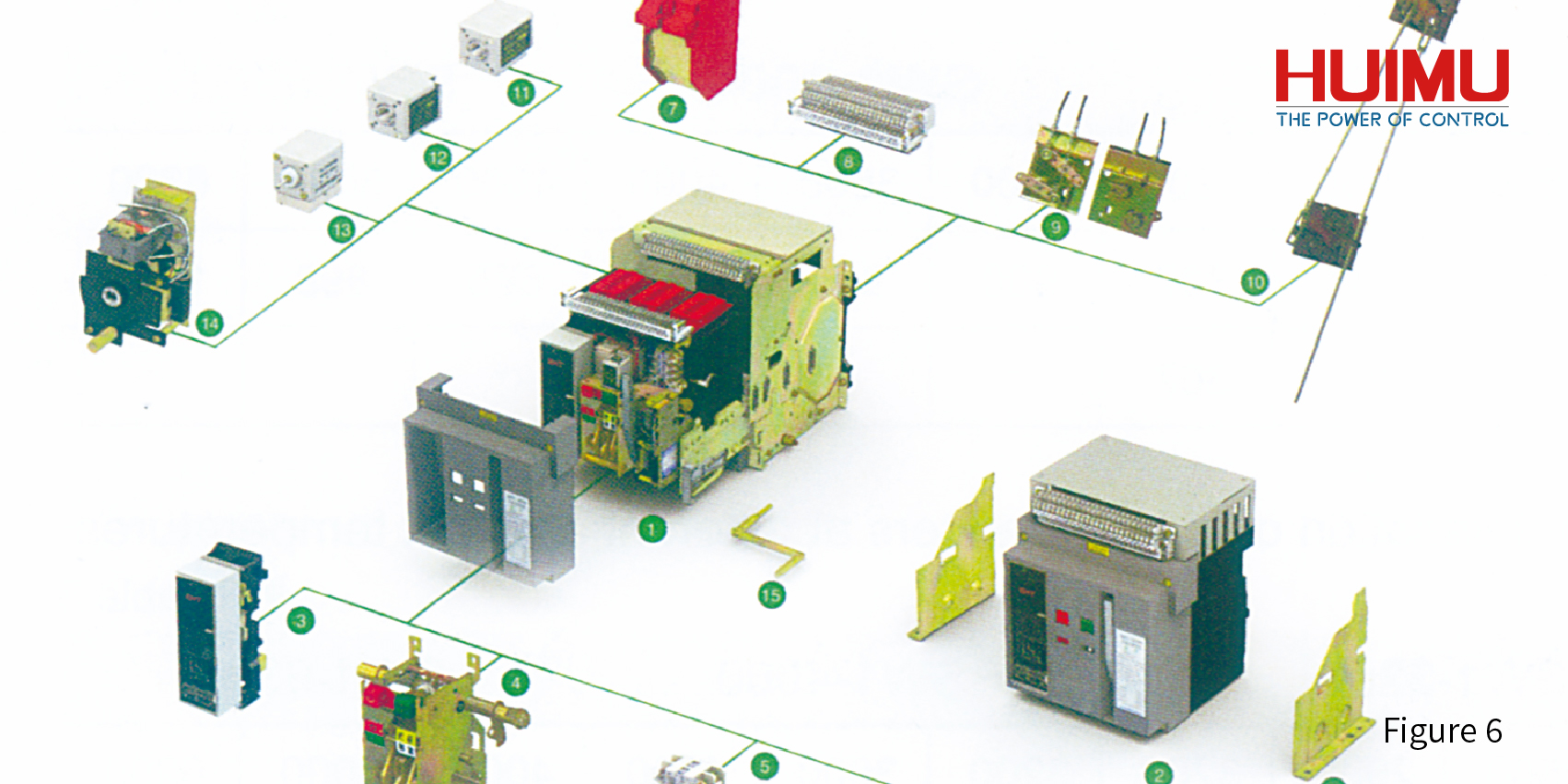
There are many types of circuit breakers. Here we mainly introduce the working principles of air circuit breakers and vacuum circuit breakers. The working principles of other types of circuit breakers are similar.
How the air circuit breaker works
Air Circuit Breaker, also called Air Switch, is a circuit breaker that uses air as the arc extinguishing medium. (As shown in Figure 3)
1.Working process when closed:
① The circuit at the arc contact is closed, and the under-voltage release starts to work. When the voltage at both ends of the release is greater than 0.85 times the rated voltage, the closing operation will be performed ②;
②The circuit of the auxiliary contact is closed, and the overload release starts to work. Only when the load current is less than the overload trip current can the closing operation be performed ③;
③The main contact is closed, and the protection functions of other releases are activated.
2.Working process when breaking:
①The protection function of any trip unit is triggered, and the circuit breaking operation is started;
② The lock hook is tripped, and each contact is disconnected one after another under the traction of the spring;
③The main contact is broken, and the surge generated by the breaking is guided to the circuit where the arc contact is located through the circuit of the under-voltage release;
④The secondary contact is broken, and the surge generated by the breaking is guided to the circuit where the arc contact is located through the circuit of the overload release;
⑤ The arc contact is broken, and the surge current generates an arc after it is broken, which disappears in the arc extinguishing chamber.
How the vacuum circuit breaker works
Vacuum circuit breaker is a circuit breaker that uses vacuum to quickly separate charged ions to block arc extinguishing. The working principle and process of the protection system can be referred to protection system, the main difference from the air circuit breaker is the arc extinguishing system. The vacuum circuit breaker has no arc contacts. When the power is cut off, an arc is directly generated on the main contact and the arc is extinguished in the vacuum interrupter. (As shown in Figure 4)
1.Working process when closed:
①The under-voltage release detects whether the voltage meets the starting conditions. When the conditions are met, it is closed and operation ② is performed.
②The main contact and static contact in the vacuum interrupter are closed, and the external circuit is turned on.
③Other trip units start to work and perform protection tasks.
2.Working process when breaking:
①Any trip unit triggers the protection mechanism to perform the breaking operation.
②The external mechanical device (Breaking Spring) pulls the movable rod where the main contact is located to move downward.
②The main contact and the static contact are disconnected, and the external circuit is disconnected and an arc containing dotted ions is generated at the same time. Charged ions diffuse rapidly in a vacuum environment, and the arc disappears.
§6. What are the applications of circuit breakers
Circuit breakers are often used in equipment that distributes electrical energy to prevent accidents of a single electrical device from affecting other electrical appliances. It usually appears in equipment such as substation boxes and switch cabinets. The following are the main application places.
Household switch cabinet
There are many electrical equipment in modern houses, and the power of all kinds of electrical equipment is different. The traditional use of fuses to protect household appliances and cannot meet people's needs. In addition, the fuse replacement operation is extremely dangerous. Therefore, various air switches are used to protect different power-consuming areas. The air switch is easy to reset and can be switched on and off repeatedly.
Distribution Cabinet
The power distribution cabinet can effectively distribute electric energy, and its internal circuit structure is complicated. In order to ensure the service life and safety of the power distribution cabinet, various circuit breakers are required to perform different protection tasks. Vacuum circuit breakers and multi-oil circuit breakers are often used here to protect corresponding load equipment under high-voltage and high-current conditions. Such as Prefabricated Substation, Outdoor Prefabricated Transformer Substation.
Motor protection
When the motor is working, it will encounter various situations, which will cause the motor to overload, under-voltage, overvoltage and so on. Motor equipment is generally very expensive. Therefore, the corresponding DC and AC circuit breakers are required to protect them to prevent them from burning out when encountering extreme conditions.
Leakage Protection
Many high-power devices will generate extremely dangerous leakage currents on their surfaces or upstream and downstream circuits during operation. Under normal circumstances, a leakage relay is used to continuously neutralize the leakage to ensure the working safety of the equipment. However, some leakage circuit breakers are still needed to preventively protect the extreme leakage current that may directly burn the equipment. Such as Metal-enclosed Ring Main Unit Switchgear, High Voltage Shunt Capacitor Compensation Switchgear

