BRIEF SAFETY MANUAL
SAFETY FIRST!
There is nothing more important than protecting your own safety.
Please strictly observe the safe operation rules and operation instruction. If you can't keep yourself safe, stop operating and leave immediately. If you encounter an uncertain or unsolvable problem, please consult the relevant technical personnel in time, please do not take risks. Before using, testing, maintaining electrical devices, you need to know the following:
§1.What are the dangers of electricity?
Electricity makes our life more convenient, but at the same time it can also causes great damage to our vulnerable body because of its enormous energy. The electric damage to the human body can be divided into: Electric Shock (such as tingling, burning sensation, spasm, paralysis, coma, ventricular fibrillation or stoppage, difficulty breathing or breathing stop); Electric Injury (such as electric burn, skin metallization). When the electric current passes through the heart, it can cause heart dysfunction, destroying the original contraction and expansion rhythm, heart failure, and ending blood circulation, causing death due to hypoxia in the brain. When the electric current passes through the central nervous system (brain and spinal cord), it can cause breathing stop and paralysis. The thermal effect of the electric current can cause electrical burns. The chemical effect of the electric current can cause electrical burns and metallization of the skin. The electromagnetic effect of the electric current will also produce radiation. The above injury may can cause secondary damage.
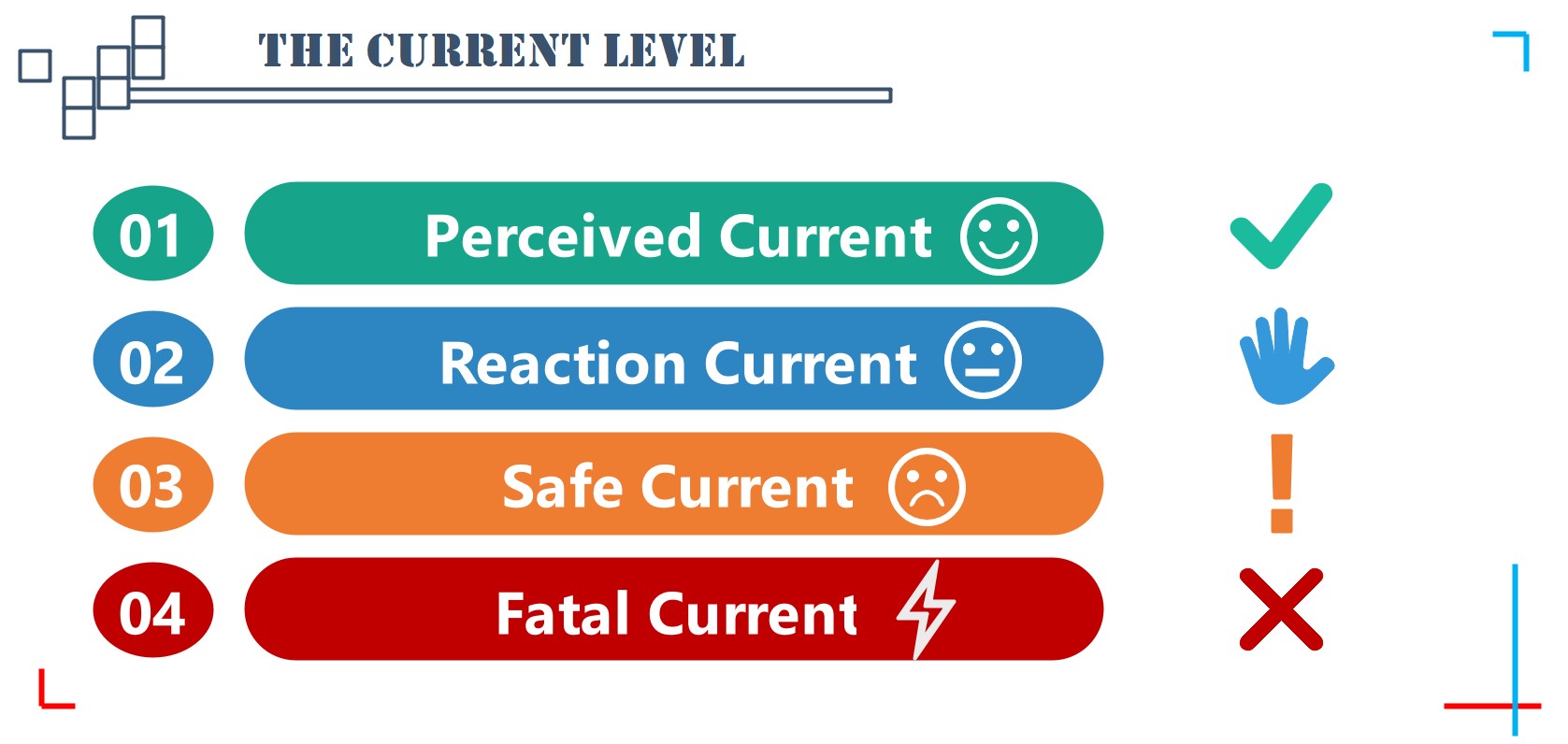
According to the different reactions of the human body after contacting the current, the current can be divided into the following four levels:
1. Perceived Current: The minimum current value that can be felt by the human body but does not cause harmful physiological reactions, which is 1mA (AC, 50~60Hz) or 5mA (DC) for adults.
2. Reaction Current: The minimum current value that can cause muscles to contract unconsciously, which is 5mA (AC, 50~60Hz) or 25mA (DC) for adult.
3. Safe Current: The maximum current value that the human body can freely get rid of the power supply without pathological damage after an electric shock, which is 10 mA (AC, 50~60Hz) or 50mA (DC) for adults.
4. Fatal Current: The minimum current value that can cause ventricular fibrillation and is life-threatening, which is typically 50 mA (AC, 50~60Hz), 80mA (DC) for adults.
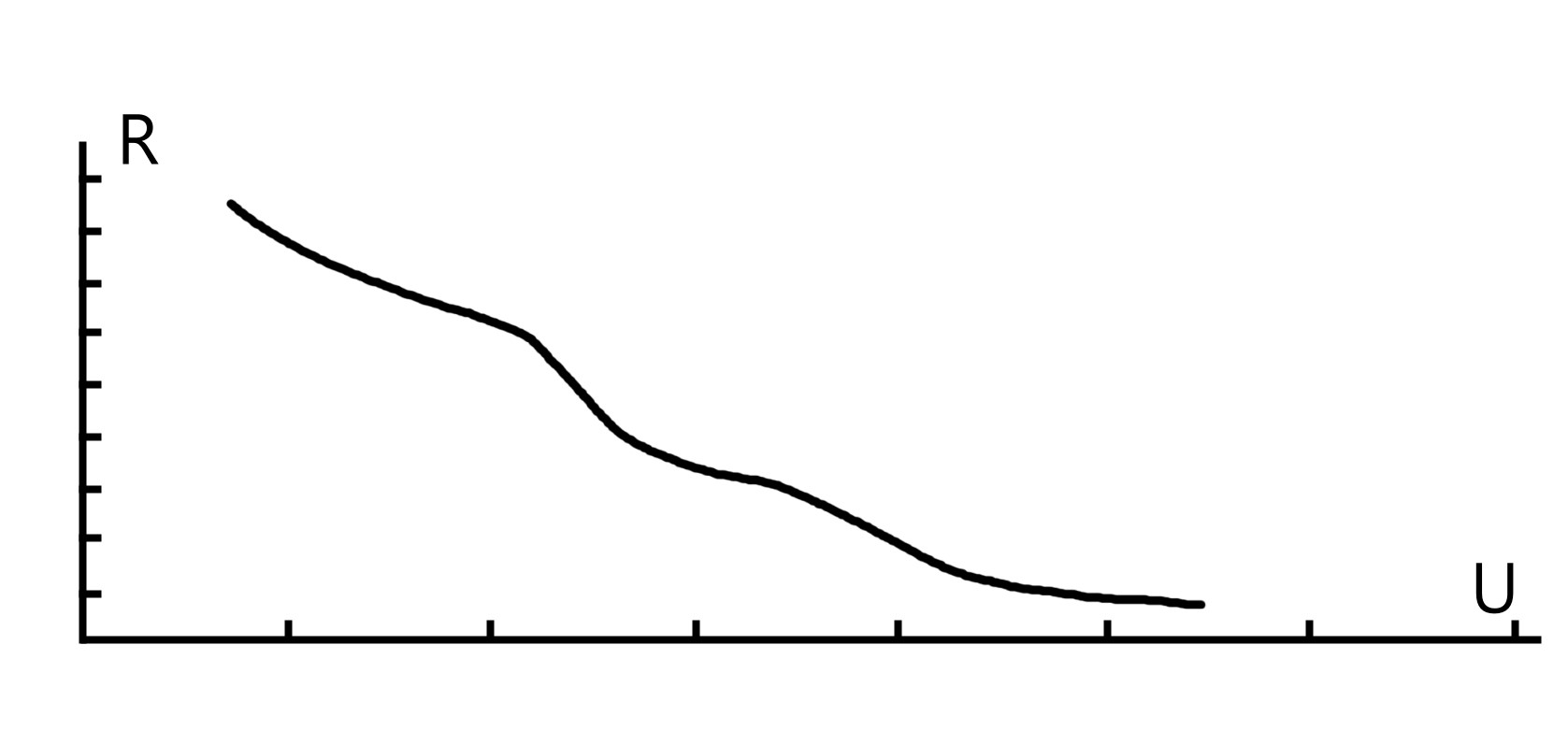
The electrical resistance of the human skin is 1000~3000Ω (normally), and 800~1000Ω (when the skin horny outer layer is destroyed), so safety voltage can be calculated according to Ohm's law (I=U/R). Since the skin resistance is affected by many factors (such as clothing, sweat, conductive dust in the air), choosing the safe voltage is more reasonable instead of the safe current. In a dry environment, the safety voltage is 24VAC (50~60Hz) or 120VDC; in a humid environment, the safety voltage is 12VAC (50~60Hz) or 40VDC.
§2. How to avoid the danger of electricity?
1. Electrical Insulation
The electrically charged object (or charged body) must be enclosed by a non-conductive insulating material. Keeping the insulation of distribution lines and electrical equipment is the most basic prerequisite to ensure personal safety and normal operation of electrical equipment. The performance of electrical insulation can be measured by its insulation resistance and dielectric strength.
2. Safety Distance
The electrically charged objects should be kept at a certain distance from the ground, the human body, other charged objects, and other facilities or equipment. Outside such safety distance, there is no danger when the human body or object is close to the charged body, such as the safety distance for the power distribution device, the maintenance safety distance, and the operation safety distance.
3. Safe Current Carrying Capacity
The safe current carrying capacity is the maximum amount of current that is allowed to continuously pass through the device. If the current exceeds the safe current carrying capacity of the device, the heat generated by the device will exceed its allowable value, which will cause damage to the insulation layer and even cause electric leakage and fire. Therefore, before selecting a device, you need to know its safe current carrying capacity.
4. Marking
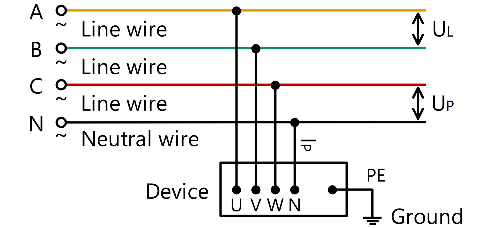
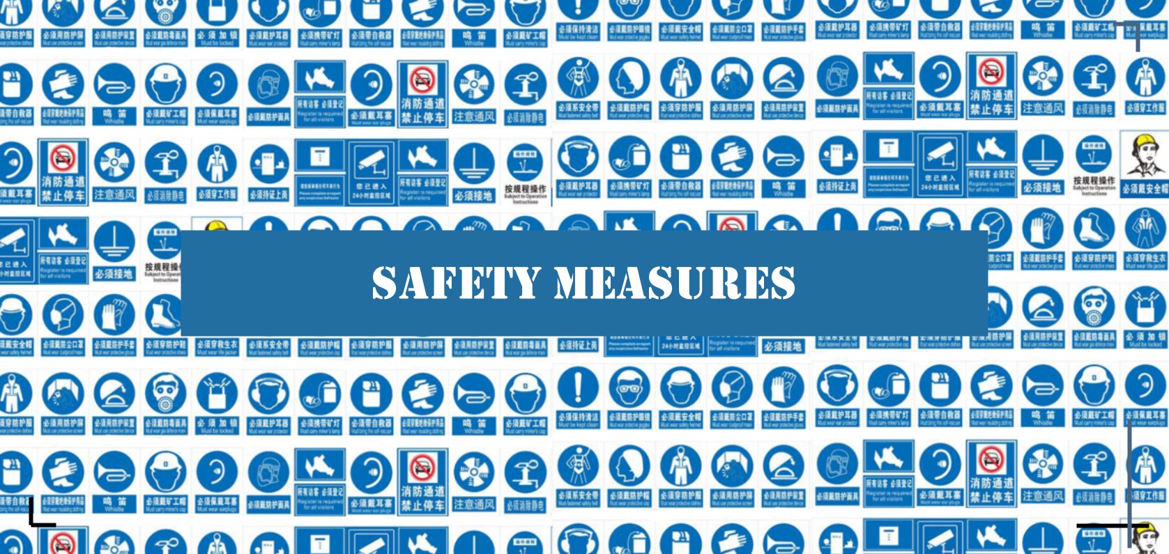
The clear, accurate and uniform marking is another important prerequisite for ensuring the safety of electricity. For instance, the hazardous zone should be marked with a warning marking, the device with different structure and different parameters can be identified with the model number marking, the wires with different nature and different purposes can be identified by color marking (For example, Phase A wire is yellow, Phase B wire is green, Phase C wire is red, exposed grounding wire is black; AC loop of secondary system circuit is yellow, the negative power supply is blue, and the signal and warning circuits are white).
§3. How to operate safely
1. Protective Equipment
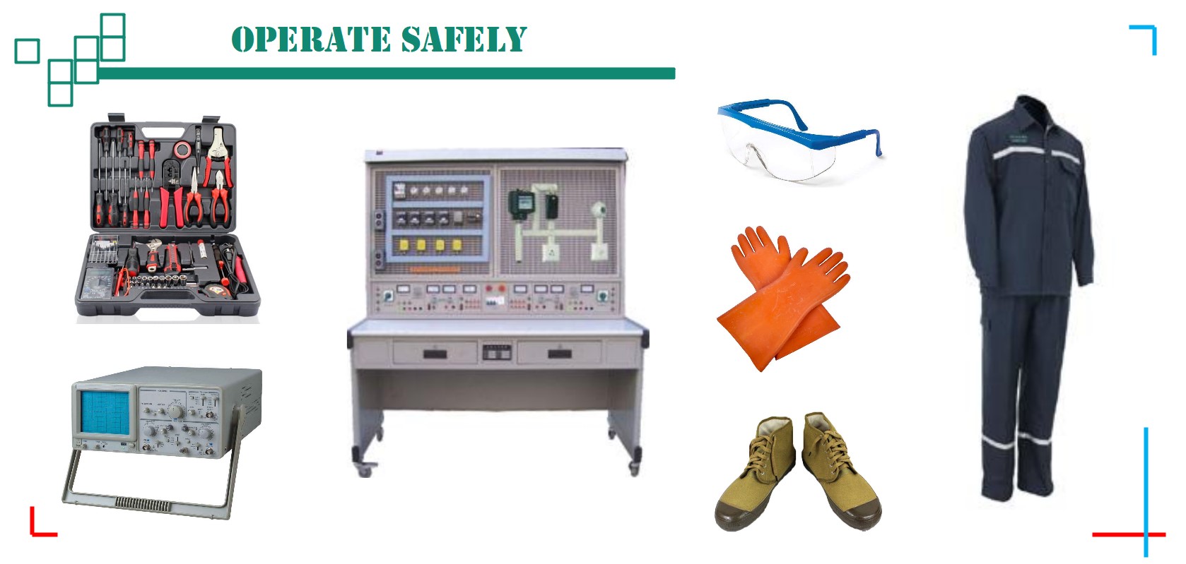
Before operating electrical device, please ensure that you have worn rubber-insulated gloves, insulated shoes, anti-static clothing, safety goggle and other protective equipment. And you also need to confirm that there are fire-fighting facilities or other safety facilities within the specified range.
2. Operating Tools
You need to check if the tool you are using has insulation ability, if the insulation material is aged and dropped, it should be replaced immediately. If there is a risk of explosion and fire, use an explosion-proof tool.
3. Operation Precautions
● Please do not operate with power.
● Please ensure that the working environment is dry, the temperature is suitable, and the ventilation conditions are good.
● Please make sure the working table is clean, and free of dust, metal debris, etc.
● Please make sure that wires are correctly connected according to the marking. For DC devices, please do not reverse the positive and negative poles.
● Please ensure that all electrical and electronic equipment is working within its rated value.
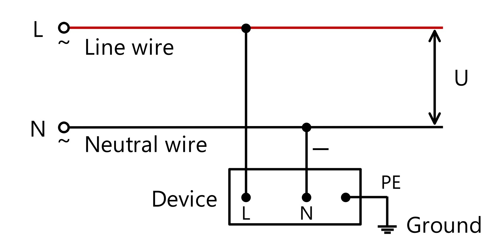
● Please make sure all the device is safely grounded.
● If there is a large capacitance or a large inductance in the device, you cannot directly touch it even after the power is turned off, because it will output a high voltage of several thousand volts in an instant. You should wait for its natural discharge or force discharge it using auxiliary equipment under safe conditions.
● Before using the voltage regulating device, make sure the regulator is in the initial state (zero voltage, 0V).
● When using electrical or electronic equipment, once you smell the burnt smell, hear abnormal sounds, see abnormal conditions such as flashing of the display or indicator light, please immediately turn off the power and check the equipment.
● If the device needs to be replaced due to a malfunction, it is recommended to use a device with the same model or technical parameters.
● Please do not press the stop button immediately after starting the electrical motor, because its starting current is 6-7 times the rated current, if it stops immediately, it will burn out other equipment.
The above content was updated on Nov. 16, 2019.
