7 steps to solve the failure of time control switch (Timer Switch)
Note: When the product fails, please disconnect the power first, and then check the equipment!
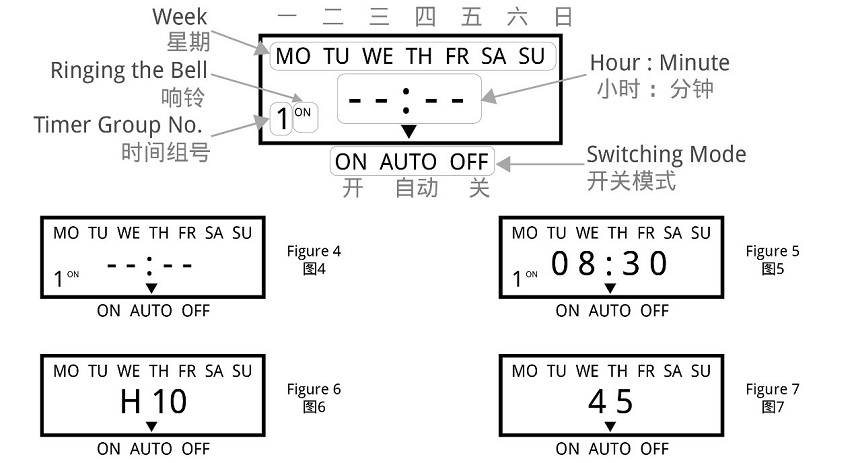
1 Check the week:
If the timer switch does not turn on or turn off the load at the set time, it may be that the "WEEK" is not adjusted correctly, please check or reset it according to the method introduced in "Timing Setting".
2 Check the time groups:
If the first point is confirmed to be correct, but the load still cannot be switched correctly on time, the reason will be that the extra time group has not been cancelled. Please refer to the method introduced in "Timing Setting" to delete it. PS: Only when the display shows "--: --", it means the time group is deleted successful; if it displays "00:00", it means 0 o'clock (24 o'clock), not the deleting success.
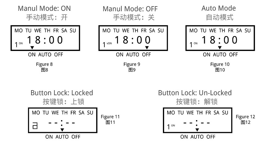
3 Check the switching mode:
If the above two points are confirmed to be correct, but the timer switch still does not work normally, it may be that the timer switch is working in "Manual Mode". You can first adjust the "AUTO/MANU" key to set the timer switch to the right working state of the load (ON or OFF), then switch to the "Automatic Mode".
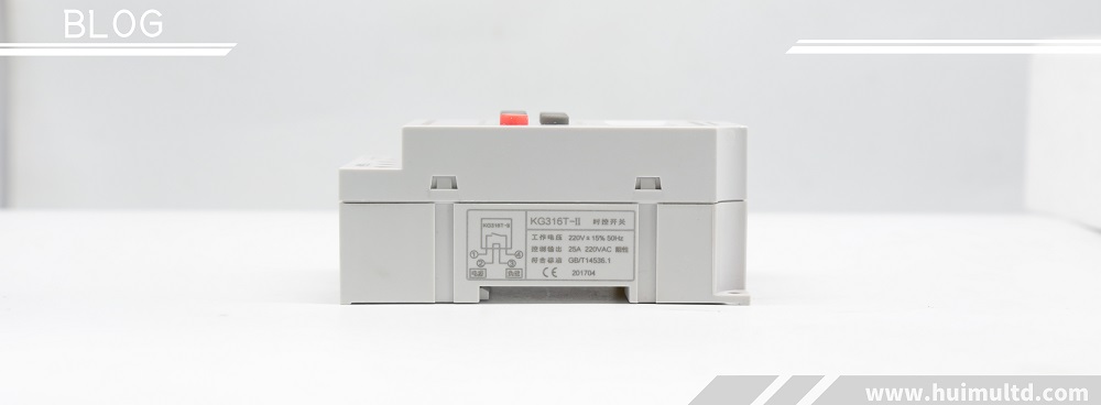
4 Check the fuse:
If the above three points are correct and the timer switch still cannot work normally, please open the rear seat insurance cover (terminal cover) and check whether the fuse has been blown. If it is blown, please replace with a new 0.1A~0.3A fuse.
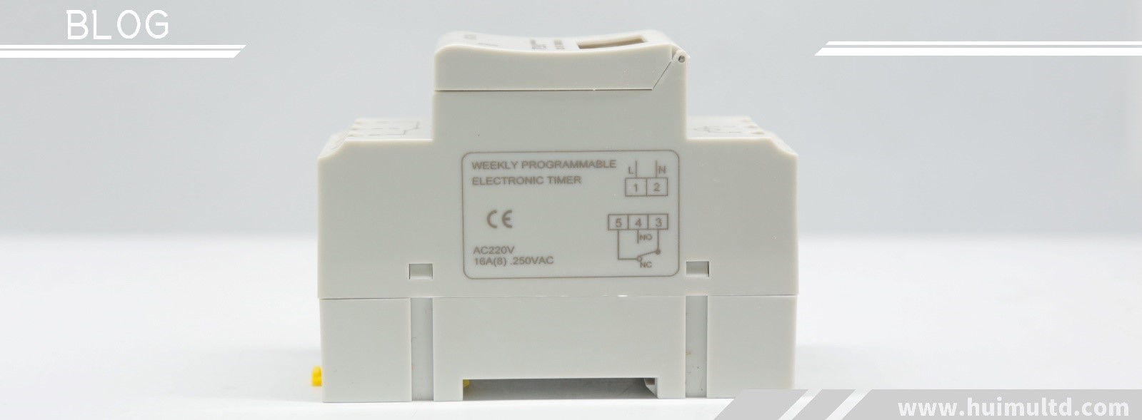
5 Check the power supply:
If the Work LED (or Output LED) is on when the timer switch is working, but the load cannot be switched normally, please check whether the voltage of the power supply is too low. If the timer switch is burned out, please check whether the power supply voltage exceeds the rated voltage of the product and whether the power cable is connected incorrectly.
6 Please replace the battery:
If the LCD screen does not display or the display is not clear, replace the battery with the same specification. (Only for timer switch with replaceable batteries)
7 Please contact us or local distributor:
If the fault cannot be eliminated by the above methods, please contact us or the distributor (dealer) in your local area.

 Introduction:
 Introduction:
 Introduction:
 Introduction:
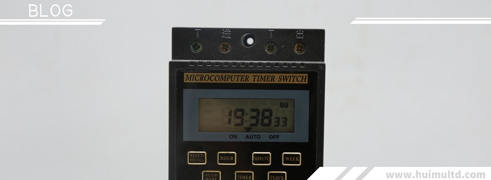

 Introduction:
 Introduction:
 Introduction:
 Introduction:
 Introduction: