Electrical Calculation
We make a list of some common calculation formulas that you might use when choosing a solid state relay (SSR)/solid state module (SSM) or designing a circuit.
Attention: HUIMU Industrial (HUIMULTD) assumes no liability for errors in data nor in safe and/or satisfactory operation of equipment designed from this information.
Electric Power Calculation Formulas
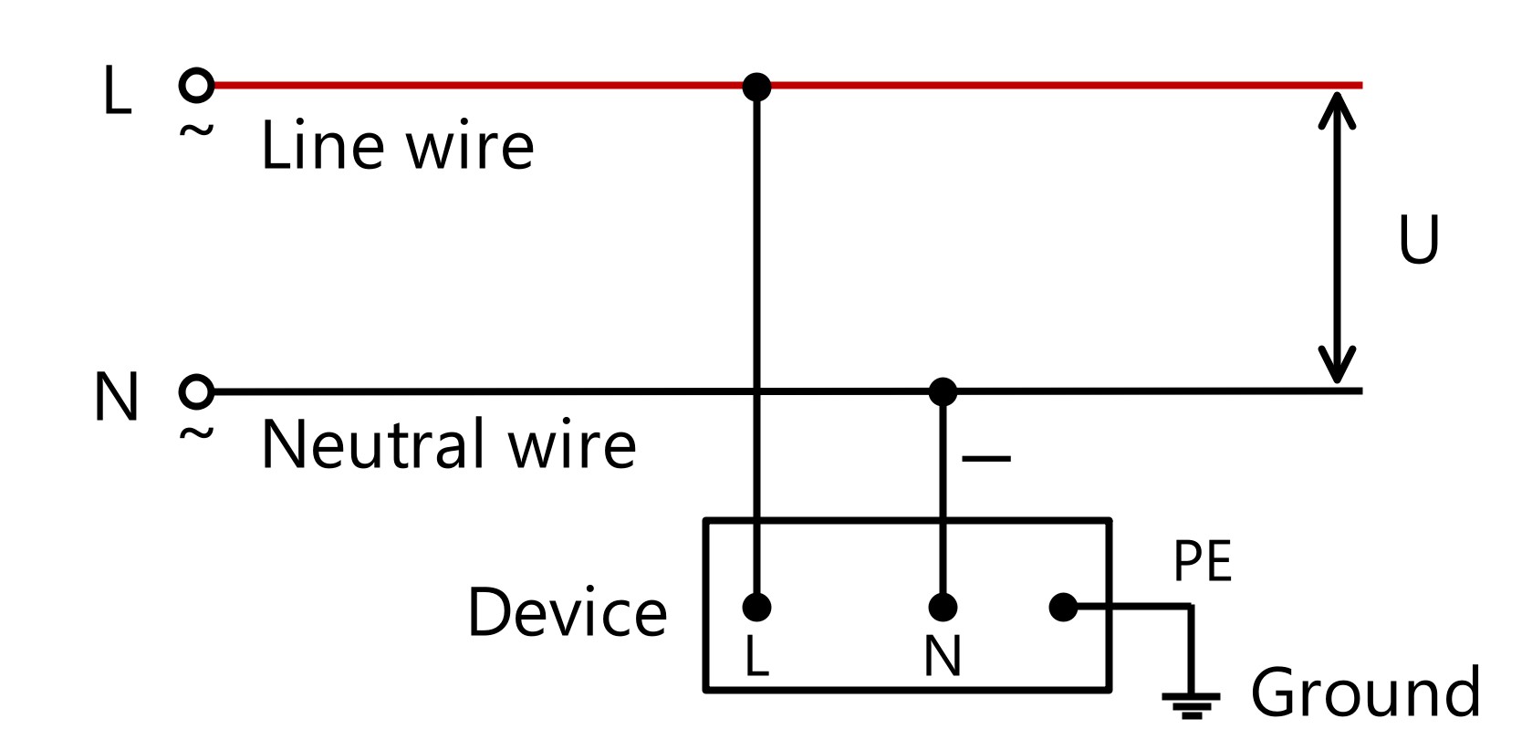
● Single Phase Load
P=U·I·cosφ
U is the Voltage (usually 220VAC), I is the Current.
U is the Voltage (usually 220VAC), I is the Current.
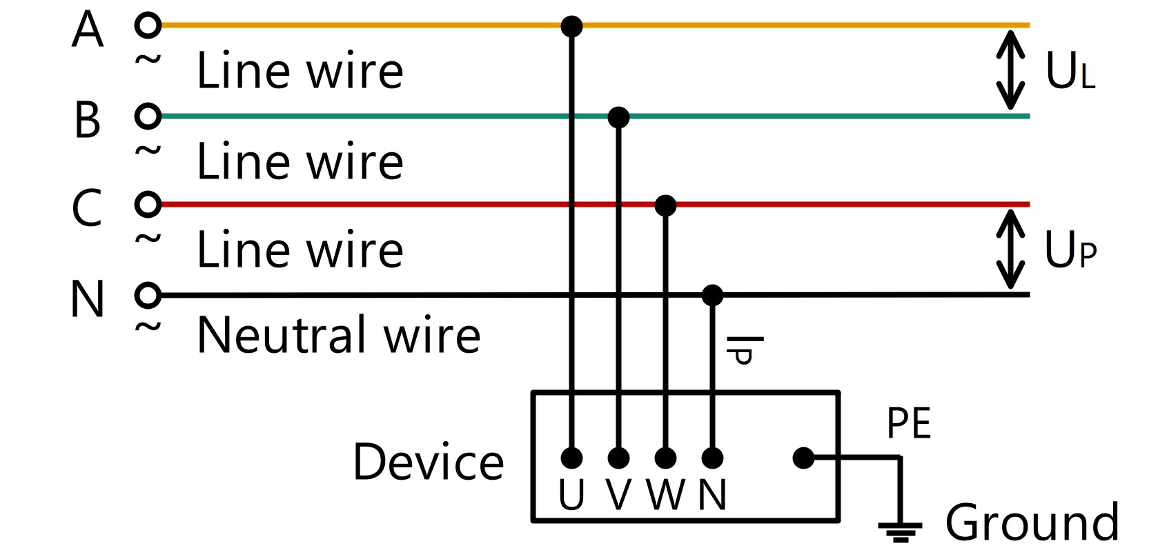
● Three Phase Load
P=√3·UL·IL·cosφ=3·UP·IP·cosφ
UL is the Line Voltage (normally 380VAC), IL is the Line Current, UP is the Phase Voltage (normally 220VAC), IP is the Phase Current.
UL is the Line Voltage (normally 380VAC), IL is the Line Current, UP is the Phase Voltage (normally 220VAC), IP is the Phase Current.
● Power Factor (cos φ)
If the load type is resistive load (such as electric heater), then cos φ=1; If the load type is inductive load (such as an electric motor), then 0<cos φ<1. Take electric motor as a example, when the electric motor is fully loaded, the active current is the largest, the reactive current is the smallest, and the power factor is about 0.85; when the load is light or no load, the active current is small, the reactive current is large, and the power factor is between 0.4 and 0.7. Thus, we usually take a power factor of 0.78 or 0.8. If the load type is capacitive load (such as power compensator), then cos φ<0.
● Peak Value, Effective Value, Average Value
The AC voltage is a sine wave, and its voltage value changes periodically from 0 to the maximum value (UMAX), so its peak value (UPK) is equal to the maximum value. The AC effective value is specified by the thermal effect of the current, that is, let an AC current and a DC current pass through resistors with the same resistance value respectively, and if they generate equal heat in the same time, then the effective value of this AC current is equaled to the value of this DC current. Since the effective value of the sinusoidal AC voltage is equal to its root mean square value (URMS or U), URMS is generally used to represent the effective value of the AC voltage. Normally, the AC voltage value we detect through detection equipment (such as multimeters) is the effective voltage value, and the AC voltage value marked on the electrical equipment is also the effective value (such as 220VAC, 380VAC). The average AC voltage (UAV) is the average voltage value over a period. The average AC voltage is equal to the integral of the voltage in one cycle divided by 2π (the time in one cycle). Theoretically, the DC voltage value obtained after full-wave rectification of the AC voltage is equal to the average value of the AC voltage.
UPK=√2·URMS=1.414·URMS
UAV=2/π·UPK=0.637·UPK
UAV=2/π·UPK=0.637·UPK
Similarly, according to Ohm's law, we can get the peak value (IPK or IMAX), the effective value (IRMS), and the average value (IAV) of the AC current.
IPK=√2·IRMS=1.414·IRMS
IAV=2/π·IPK=0.637·IPK
IAV=2/π·IPK=0.637·IPK
Because the value of DC current or DC voltage is constant, they have no maximum value, effective value, and average value.
Derating Factor Calculation Formulas
Since the performance of the solid state relay/solid state module is affected by the working environment and the load type, the Derating Factor (or Current Multiple Factor) should be considered when selecting the rated current value of the solid state relay/solid state module.

IR=IL/α
IR is the rated current value of the solid state relay/solid state module;
IL is the DC load current value or the AC load current effective value (rms value);
α is the derating factor.
IR is the rated current value of the solid state relay/solid state module;
IL is the DC load current value or the AC load current effective value (rms value);
α is the derating factor.
According to the working environment of the solid state relay/solid state module (ventilation, temperature, service time, etc.), the derating factor can be divided into three levels: Protected, Normal and Severe.
For resistive loads (such as electric heater, incandesc ent lamp, etc.), α = 0.5 (Protected), α = 0.5 (Normal), α = 0.3 (Severe);
For inductive loads (such as motor, transformer, etc.), α = 0.2 (Protected), α = 0.16 (Normal), α = 0.14 (Severe);
For capacitive loads (such as power compensator, etc.), α = 0.2 (Protected), α = 0.16 (Normal), α = 0.14 (Severe).

Current Multiple Factor is the inverse of Derating Factor.
IR=IL·β
IR is the rated current value of the solid state relay/solid state module;
IL is the DC load current value or the AC load current effective value (rms value);
β is the current multiple factor.
IR is the rated current value of the solid state relay/solid state module;
IL is the DC load current value or the AC load current effective value (rms value);
β is the current multiple factor.
For resistive loads (such as electric heater, incandescent lamp, etc.), β = 2 (Protected), β = 2 (Normal), β = 3 (Severe);
For inductive loads (such as motor, transformer, etc.), β = 5 (Protected), β = 6 (Normal), β = 7 (Severe);
For capacitive loads (such as power compensator, etc.), β = 5 (Protected), β = 6 (Normal), β = 7 (Severe).
For inductive loads (such as motor, transformer, etc.), β = 5 (Protected), β = 6 (Normal), β = 7 (Severe);
For capacitive loads (such as power compensator, etc.), β = 5 (Protected), β = 6 (Normal), β = 7 (Severe).
For example, if you need a DC to AC Panel solid state relay to switch a 220VAC, 10A resistive load, and require this solid state relay to work uninterrupted in a poor ventilation environment, then according the derating factor β = 3 (Severe), you should choose MGR-1D4830 (DC to AC, load: 480VAC, 30A).
Varistor Calculation Formulas
If the load peak voltage is high, be sure to connect the varistor (such MOV, ZNR) in parallel to the output terminal of the solid state relay/ solid state module.
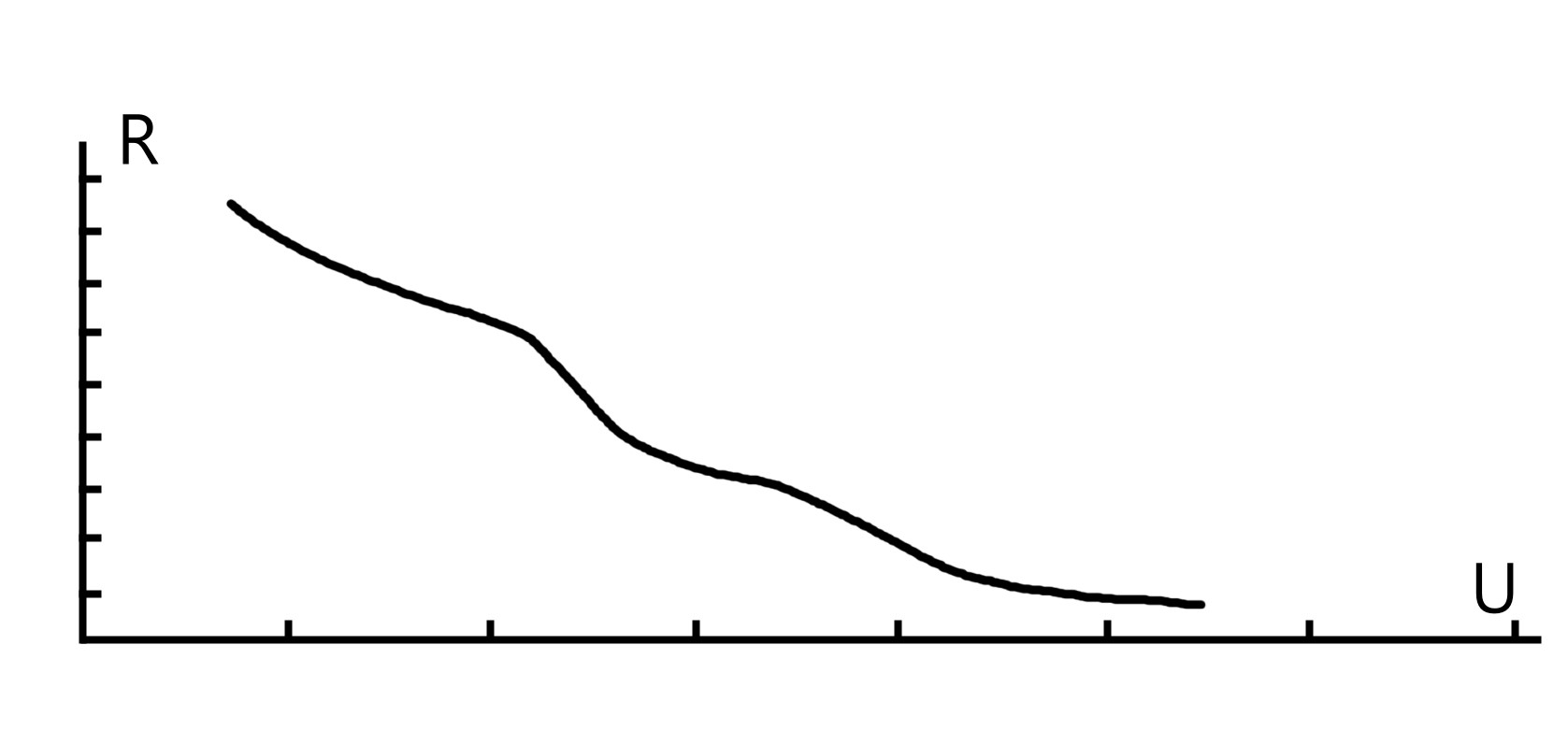
VimA=V1mA=(a·v)/(b·c)
VimA is the varistor voltage when the current is XmA. Due to the current value is usually set at 1mA, it can also be expressed as V1mA; a is the voltage fluctuation coefficient, generally 1.2; b is the varistor error value, generally 0.85; c is the aging coefficient of the component, generally 0.9; v is the DC operating voltage, or the AC rms voltage.
VimA is the varistor voltage when the current is XmA. Due to the current value is usually set at 1mA, it can also be expressed as V1mA; a is the voltage fluctuation coefficient, generally 1.2; b is the varistor error value, generally 0.85; c is the aging coefficient of the component, generally 0.9; v is the DC operating voltage, or the AC rms voltage.
Therefore, the above formula can be simplified as:
For DC circuit,VimA≈1.6·v
For AC circuit,VimA≈1.6·Vp=1.6·√2·VAC
Vp is the peak voltage, VAC is the effective value.
For DC circuit,VimA≈1.6·v
For AC circuit,VimA≈1.6·Vp=1.6·√2·VAC
Vp is the peak voltage, VAC is the effective value.
Generally, the varistor voltage is 1.6 times the load voltage, but when the load is an inductive load, the varistor voltage should be 1.6-1.9 times the load voltage to ensure safety.
Rectifier Circuit Calculation Formulas
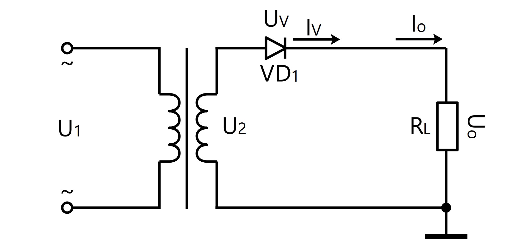
● Single-Phase Half-Wave Rectification Circuit
U0=0.45·U2
I0=0.45·U2/RL
IV=I0
URM=√2·U2
I0=0.45·U2/RL
IV=I0
URM=√2·U2
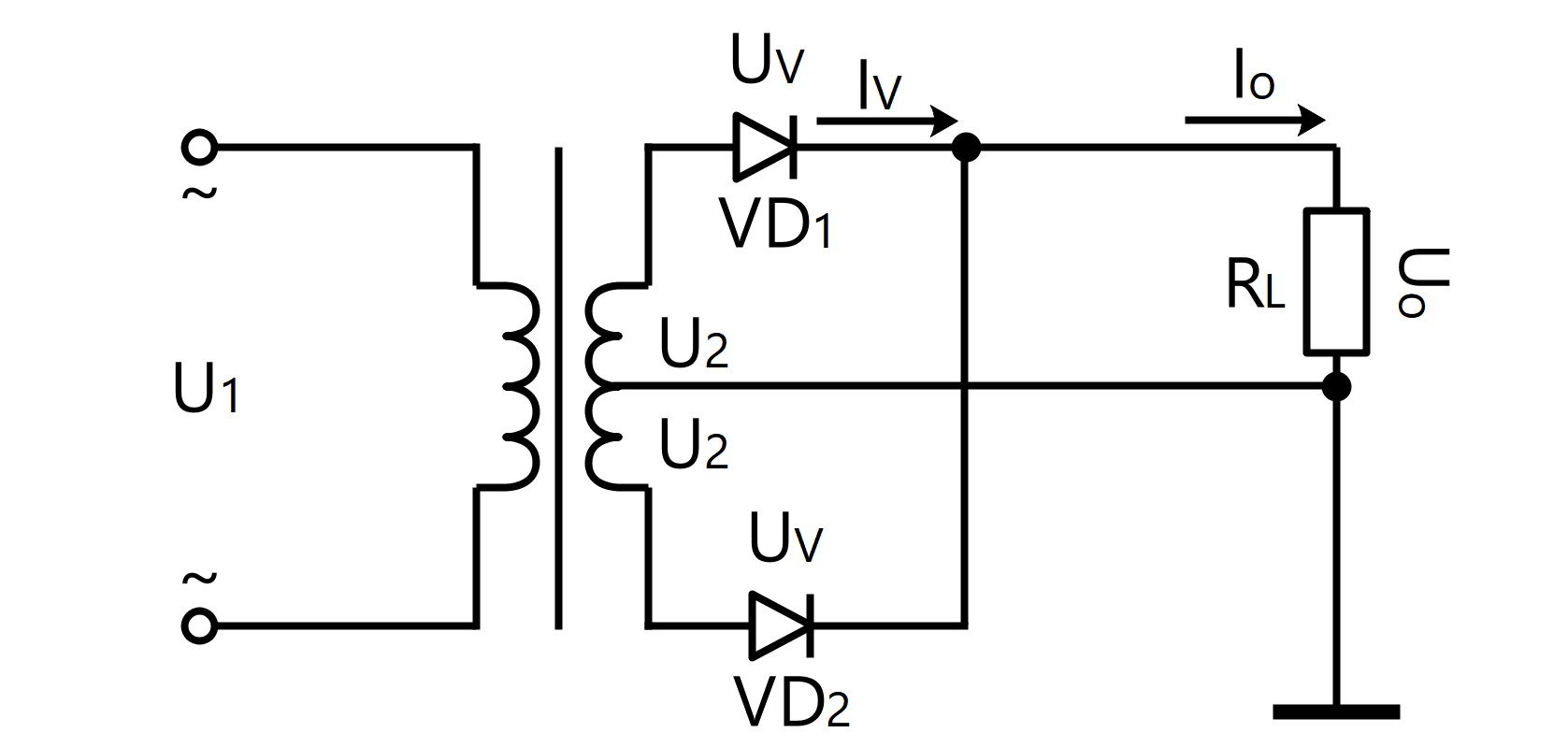
● Single-Phase Full-Wave Rectification Circuit
U0=0.9·U2
I0=0.9·U2/RL
IV=1/2·I0
URM=2·√2·U2
I0=0.9·U2/RL
IV=1/2·I0
URM=2·√2·U2
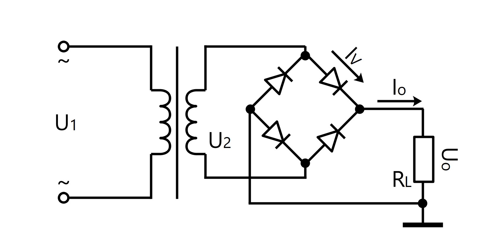
● Single-Phase Bridge Rectification Circuit
U0=0.9·U2
I0=0.9·U2/RL
IV=1/2·I0
URM=√2·U2
I0=0.9·U2/RL
IV=1/2·I0
URM=√2·U2
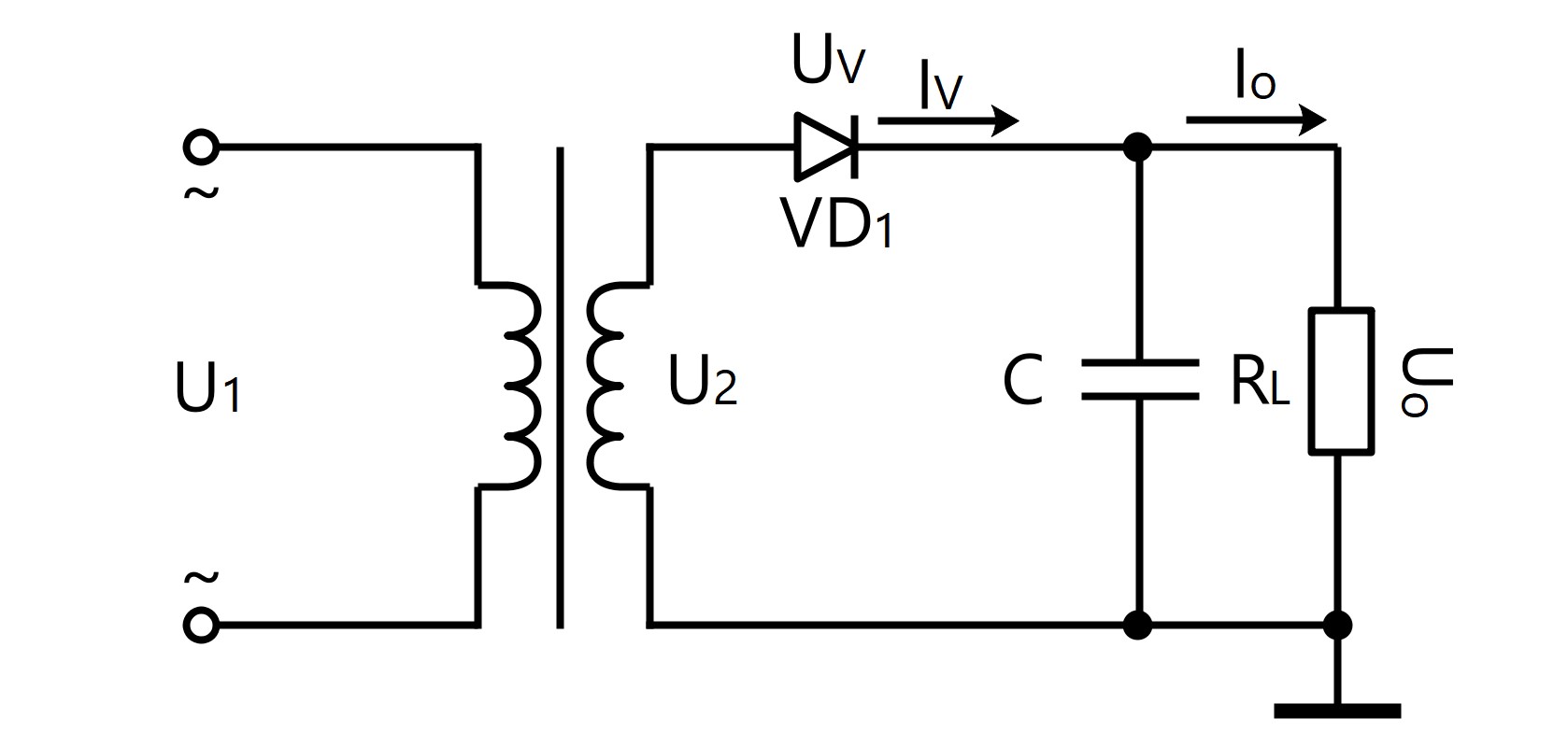
● Single-Phase Half-Wave Rectification Filter Circuit
U0=U2
I0=U2/RL
Iv=1/2·I0
URM=2·√2·U2
C≥(3~5)·T/RL
T=1/f, if f=50Hz, then T=1/50=20ms
I0=U2/RL
Iv=1/2·I0
URM=2·√2·U2
C≥(3~5)·T/RL
T=1/f, if f=50Hz, then T=1/50=20ms
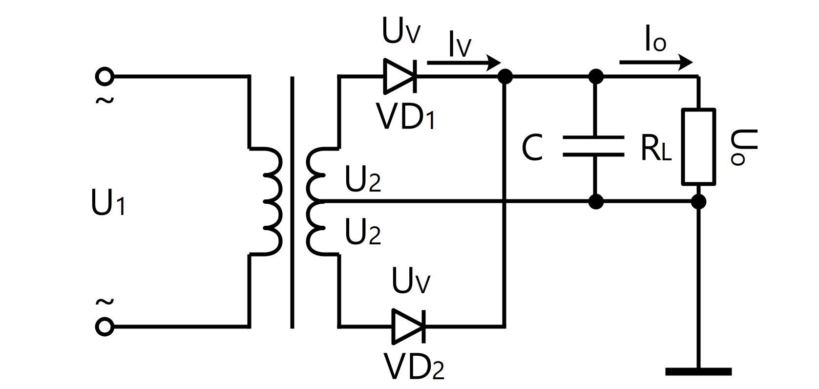
● Single-Phase Full-Wave Rectification Filter Circuit
U0=1.2·U2
I0=1.2·U2/RL
Iv=1/2·I0
URM=√2·U2
C≥(3~5)·T/2RL
T=1/f, if f=50Hz, then T=1/50=20ms
I0=1.2·U2/RL
Iv=1/2·I0
URM=√2·U2
C≥(3~5)·T/2RL
T=1/f, if f=50Hz, then T=1/50=20ms
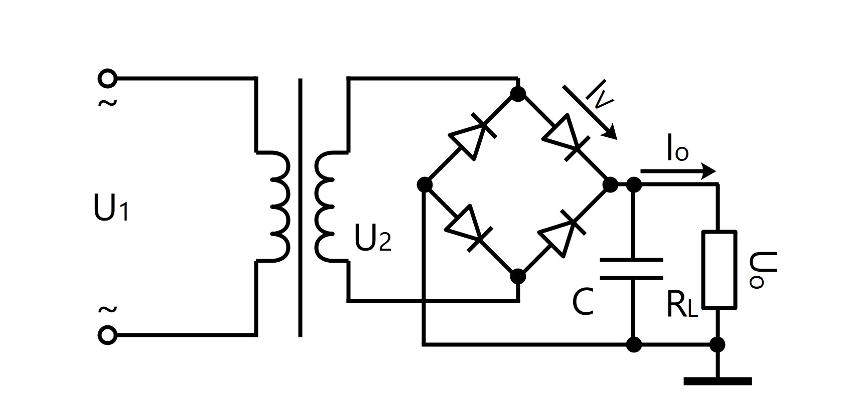
● Single-Phase Bridge Rectification Filter Circuit
U0=1.2·U2
I0=1.2·U2/RL
Iv=1/2·I0
URM=√2·U2
C≥(3~5)·T/2RL
T=1/f, if f=50Hz, then T=1/50=20ms
I0=1.2·U2/RL
Iv=1/2·I0
URM=√2·U2
C≥(3~5)·T/2RL
T=1/f, if f=50Hz, then T=1/50=20ms
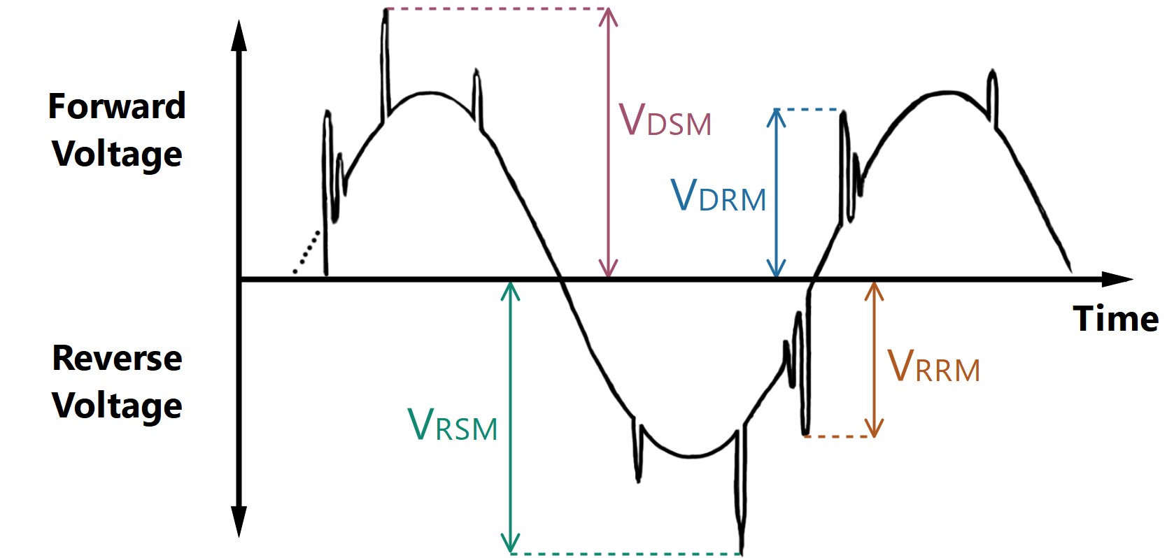
VRSM=VRRM+200V
VRSM (Non-Repetitive Peak Reverse Voltage), is the maximum allowable surge value of reverse voltage that can be applied to the reverse direction of the device; VRRM (Repetitive Peak Reverse Voltage), is the maximum allowable value of reverse voltage that can be repeatedly applied to the reverse direction of the device.
VRSM (Non-Repetitive Peak Reverse Voltage), is the maximum allowable surge value of reverse voltage that can be applied to the reverse direction of the device; VRRM (Repetitive Peak Reverse Voltage), is the maximum allowable value of reverse voltage that can be repeatedly applied to the reverse direction of the device.
VDSM =VDRM +200V
VDSM (Non-Repetitive Peak Off-State Voltage), is the maximum allowable surge value of off-state voltage that can be applied to the forward direction of the device; VDRM (Repetitive Peak Off-State Voltage), is the maximum allowable value of off-state voltage that can be repeatedly applied to the forward direction of the device.
VDSM (Non-Repetitive Peak Off-State Voltage), is the maximum allowable surge value of off-state voltage that can be applied to the forward direction of the device; VDRM (Repetitive Peak Off-State Voltage), is the maximum allowable value of off-state voltage that can be repeatedly applied to the forward direction of the device.
It2=ITSM2·tw/2
tw is the half sine period; ITSM it the maximum non-repetitive on-state surge current in one cycle; if the frequency is 50Hz, It2=0.005 ITSM2 (Amps2·sec)
tw is the half sine period; ITSM it the maximum non-repetitive on-state surge current in one cycle; if the frequency is 50Hz, It2=0.005 ITSM2 (Amps2·sec)
Heat Generation Calculation Formulas
When the solid state relays are working, the output circuit has a voltage drop of 1~2V. When the solid state modules (or power modules) are working, the output circuit has a voltage drop of 2~4V. And the electrical energy they consume is transmitted as heat, and this heat is only related to their operating current. The solid state relay has a calorific value of 1.5 watts per ampere (1.5 W/A) and the solid state module has a calorific value of 3.0 watts per ampere (3.0 W/A). The heat generated by the three-phase circuit is the sum of the heat generated by each phase.
Single Phase or DC solid state relay: P=1.5·I
Single Phase or DC solid state module: P=3.0·I
P is the heat generated by solid state relay/solid state module, and the unit is W; I is the actual load current, and the unit is A.
Single Phase or DC solid state module: P=3.0·I
P is the heat generated by solid state relay/solid state module, and the unit is W; I is the actual load current, and the unit is A.
Normally, if the load current is 10A, a heat sink must be equipped. If the load current is 40A or higher, an air-cooled or water-cooled heat sink must be equipped.
Heat Dissipation Calculation Formulas
The heat dissipation performance of the heat sink is related to its material, shape, temperature difference, and etc.
Q=h·A·η·ΔT
Q is the heat dissipated by the heat sink; h is the total thermal conductivity of the heat sink (W/cm2·°C), generally aluminum material is about 2.12W/cm2·°C, the copper material is about 3.85W/cm2·°C, and the steel material is about 0.46W/cm2 °C; A is the surface area of the heat sink (cm2); η is the heat sink efficiency, which is mainly determined by the shape of the heat sink; ΔT is the difference between the maximum temperature of the heat sink and the ambient temperature (°C).
Q is the heat dissipated by the heat sink; h is the total thermal conductivity of the heat sink (W/cm2·°C), generally aluminum material is about 2.12W/cm2·°C, the copper material is about 3.85W/cm2·°C, and the steel material is about 0.46W/cm2 °C; A is the surface area of the heat sink (cm2); η is the heat sink efficiency, which is mainly determined by the shape of the heat sink; ΔT is the difference between the maximum temperature of the heat sink and the ambient temperature (°C).
Therefore, it can be obtained from the above formula that the larger the surface area of the heat sink is, the larger the difference from the ambient temperature is, and the better the heat dissipation performance is.
Common Unit Conversion
1MΩ=103kΩ=106Ω=109mΩ
1F=103mF=106μF=109nF=1012pF
1H=103mH=106μH
1MV=103kV=106V=109mV=1012μH
1kA=103A=106mA=109μA
1W=103mW=1J/s=1V·A
1HP=0.75kW
1kW·h=103W·h=103V·A·h=106 V·mA·h=3.6·106J
1cm=10mm=0.39in
1cm2=0.16sq in
°F=1.8°C+32
K=°C+273.15
1F=103mF=106μF=109nF=1012pF
1H=103mH=106μH
1MV=103kV=106V=109mV=1012μH
1kA=103A=106mA=109μA
1W=103mW=1J/s=1V·A
1HP=0.75kW
1kW·h=103W·h=103V·A·h=106 V·mA·h=3.6·106J
1cm=10mm=0.39in
1cm2=0.16sq in
°F=1.8°C+32
K=°C+273.15
The above content was updated on Nov. 29, 2019.
There may be errors and omissions during the content collation and upload process, so all things above are for reference only. If you find any problems, your correction will be grateful.
There may be errors and omissions during the content collation and upload process, so all things above are for reference only. If you find any problems, your correction will be grateful.
