§1. What is a Power Module
In this chapter you will learn what are solid state modules.
The power module (PM) is also called electronic power module, or solid state power module, which is a module that encapsulates power electronic components combination into a solid state structure according to a certain functional. Through the internal integrated circuit (IC), the power module can output the power and adjust the power of the load. According to the main functions, we divide solid-state modules into solid state voltage regulation modules and solid state rectification modules.
1.1 Solid State Voltage Regulation Module
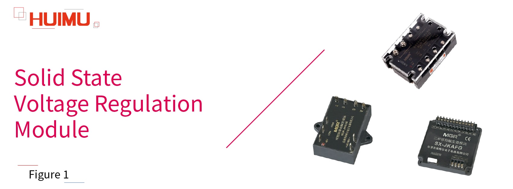 The solid state voltage regulation module (also known as the solid state power voltage regulation module, the solid state power regulating module, the solid state voltage regulating module and the solid state power voltage regulator module) are used to adjust the voltage or power of the AC load. Generally, the solid state voltage regulating module is integrates the synchronous transformer, the power output circuit, the phase shift circuit, the detection circuit, and can be directly connected to the load to control it. Solid state voltage regulator modules are widely used into various fields, such as scientific research, experiment, detection, heating insulation, soft start.
The solid state phase-shift module (or solid state phase-shifting module) is a type of voltage-regulating module, but it can only output a phase-shifting signal and cannot be directly connected to the load. Generally, it requires a set of solid-state relays (or power thyristor circuits) and a synchronous transformer to achieve the voltage regulation function.
According to the phase, the solid-state voltage regulating module can be divided into: single-phase solid-state voltage regulator modules, three-phase solid-state voltage regulator modules.
According to whether the loop is closed, the solid-state voltage regulating module can be divided into closed-loop type and open-loop type (unclosed-loop type)
According to whether the strong current parts and weak current parts are isolated, the solid-state voltage regulating module can be divided into full isolation type and non-full isolation type.
According to the number of controlled loads (channels), the solid-state phase-shift module can be divided into: single channel solid-state phase-shift module (or single phase solid-state phase-shift module), dual channel solid-state phase-shift module, three channel solid-state phase-shift module (or three phase solid-state phase-shift module).
According to the external power output device, the solid-state phase-shift module can be divided into: external solid state relay type phase-shift modules, and external thyristor power circuit type phase-shift modules.
1.2 Solid State Rectification Module
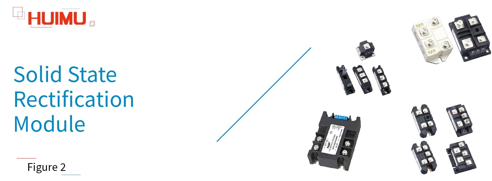
The solid state rectification module (or solid state rectifier module) uses power components (such as power diodes, power thyristors, rectifier bridges) to rectify Alternating Current (AC) into Pulsating Direct Current (Pulsating DC) or Rectified Alternating Current, whose direction (positive and negative) does not change, but the magnitude changes with time. In addition, Solid State Diodes and Rectifier Silicon are uncontrollable devices, and Semiconductor Control Rectifier and Unidirectional thyristor are controllable devices. Solid state rectification modules are widely used into various fields, such as the DC power supply of instruments, the input rectified power supply of PWM inverter, the excitation power supply of DC motor, the input rectification system of switching power supply, the soft-start capacitor charging system, the electric drive and auxiliary current, the inverter welding machine, the DC power charging system.
According to the phase, solid-state rectifier relays can be divided into: single-phase solid-state rectifier relays, three-phase solid-state rectifier relays.
According to the phase, solid-state bridge rectifiers can be divided into: single-phase solid-state bridge rectifiers, three-phase solid-state bridge rectifiers.
According to the amount of rectifier silicon (or diode), solid-state rectifier modules can be divided into: half-wave rectifier modules, full-wave rectifier modules (half-bridge rectifier modules), and full-bridge rectifier modules. The half-wave rectifier module has only one rectifier silicon (or diode), the full-wave rectifier module (half-bridge rectifier module) has two rectifier silicon (or diodes), and the full-bridge rectifier module has four rectifier silicon (or diodes). The full-wave rectifier modules have the similar function as the full-bridge rectifier modules, but the cost of the full-bridge type is higher than the full-wave type, and the requirements on the transformer are lower than the full-wave type.
According to whether the strong current parts and weak current parts are isolated, solid-state rectifier modules can be divided into fully isolated and non-fully isolated.
According to the composition of diodes and thyristors, solid-state rectifier modules can be divided into uncontrolled rectifier modules, fully-controlled rectifier modules and half-controlled rectifier modules. The output components of the uncontrolled rectifier module are completely composed of rectifier diodes. The output components of the fully controlled rectifier module are composed of thyristors. The output components of half-controlled rectification are composed of diode and thyristor.
§2. How does Power Module works
In this chapter you will learn how do electronic power modules work.
2.1 The Working Principle of Solid State Voltage Regulation Module
Take our MGR-DT series single phase voltage regulation module as an example. The MGR-DT series consists of a synchronous transformer, a phase detection circuit, a phase shift trigger circuit, and a thyristor output circuit. MGR-DT accepts two control modes (automatic control and manual control), and four control signals (0-5VDC, 0-10VDC, 1-5VDC, 4-20mA). Automatic mode, that is, the control signal applied to the solid-state voltage regulator is generated by PLC or computer system. Manual control mode, that is, the 0-5VDC control signal is generated by manually controlling a potentiometer under the 5VDC internal power supply.
The wiring of MGR-DT series:
Ports 1 and 2 are the power output ports of the solid-state voltage regulator module. The load and power supplier can be directly connected to the output port of the voltage regulator module. Because the voltage and current of the inductive load are not synchronized, and will be charged and discharged during the power-on and power-off process, we will use a pure resistive load to describe the working process by default.
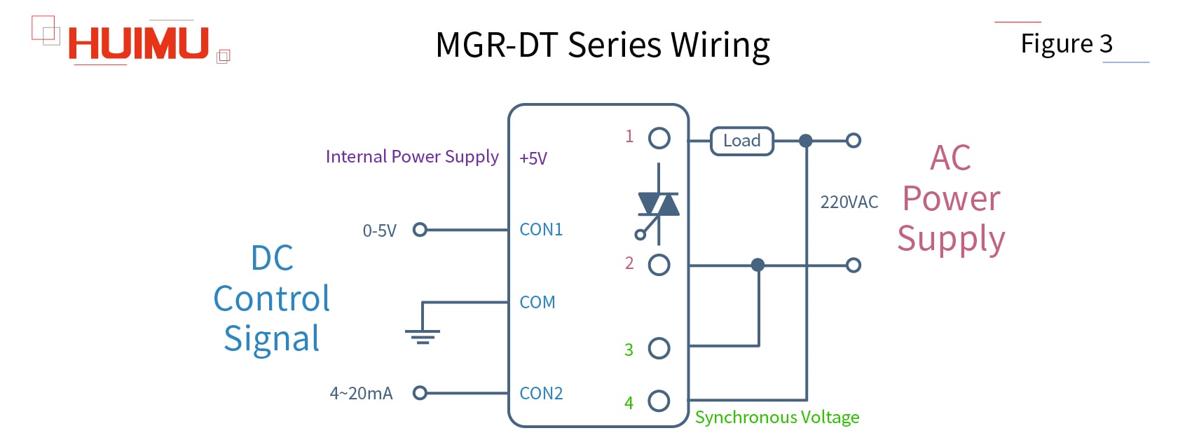
Ports 3 and 4 are connected to the built-in synchronous transformer of the solid-state voltage regulator module. The role of the synchronous transformer is to provide the thyristor in the module with a signal synchronized with the AC voltage of the power supply to ensure that the load voltage can be adjusted accurately without causing output delays and voltage errors. CON1 and CON2 are input ports for automatic control signal; + 5V is the power generated inside the solid-state voltage regulator module, which is used to supply the potentiometer and connected to the high potential side of the potentiometer; COM is the common terminal, and COM port will be grounded if the automatic control mode is chosen, and will be connected to the low potential side of the potentiometer if manual control mode is selected.
The working process of MGR-DT series:
Before explaining the working principle of the voltage regulator module, we need to know that the voltage of the alternating current (AC) alternates periodically from 0 to the peak. And it is not the instantaneous voltage that does the work on the load, but the effective AC voltage which is thermodynamically equivalent to the DC voltage. By changing the time that the AC voltage does work in a cycle, it is possible to change its effective voltage value. We normally use the thyristor for voltage regulation, because it is a controllable component, and its conduction ability can be adjusted by adjusting the signal applied on its control electrode (gate). This ability can be represented by the conduction angle α on the AC voltage curve. In addition, there is a quantity corresponding to α called the control angle θ, their relationship is θ + α = π (180 °), so the larger the conduction angle, the smaller the control angle.
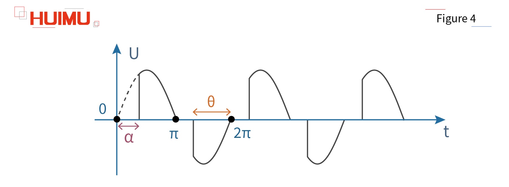
We choose CON0-5VDC as the control signal, and the control voltage rises from 0 to 5VDC. Because the starting voltage (trigger voltage) of the unidirectional thyristors (SCR) is 0.8VDC, if the voltage is less than 0.8VDC, the thyristor is turned off, that is, the solid-state voltage regulating module does not work. When the voltage reaches 0.8VDC, although the transistor starts to work, its conduction angle α is 180 °, so the voltage regulator module does not output any power at this time. When the voltage is adjusted from 0.8 to 5VDC, the conduction angle α is smoothly adjusted from 180 ° to 0 °. At this time, the effective value of the output voltage is adjusted from 0 to the maximum value of the power grid. But the saturation voltage of the thyristor is 4.6VDC, so if the voltage reaches 4.6VDC, the thyristor saturates and the output voltage reaches the maximum value, at this time, no matter how much the control voltage is increased, the output voltage will not change.
2.2 The Working Principle of Solid State Rectification Module
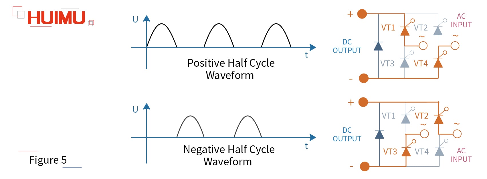
Take MHF series single phase fully control rectifier module as an example. The MHF series rectifier module contains 4 unidirectional thyristors (SCR), VT1, VT2, VT3, VT4. And VT1 and VT4 constitute a pair of bridge arm, and VT2 and VT3 constitute another pair of bridge arm. Two pairs of bridge arms form the full bridge rectifier. When the input voltage U is in the positive half cycle, the current direction is VT1-R-VT4; when the input voltage U is in the negative half cycle, the current direction is VT2-R-VT3.
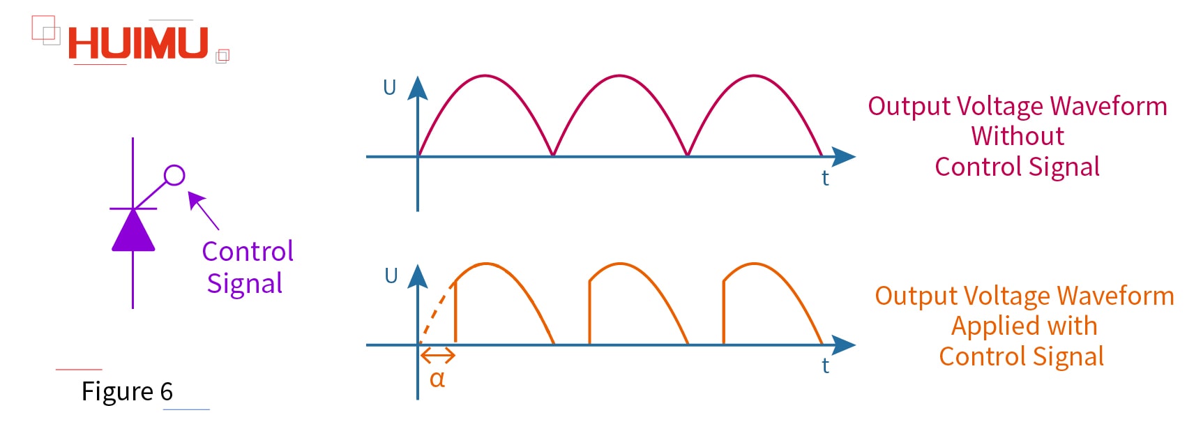
In addition to the rectification function, we can apply a control signal to the control pole (gate) of the unidirectional thyristor. By adjusting the conduction angle α of the thyristors, its output waveform and output voltage value can be changed, which is similar to the phase-shift process of voltage regulation module.
§3. How to select the Power Module
3.1 Voltage Regulator
3.1.1 Single Phase
Standard Potentiometer Type: MGR-R series
Industrial Potentiometer Type: MGR-HVR series
Analog Signal/Continuous Voltage Type: MGR-1VD series
Digital Signal/Pulse Voltage Type: MGR_DV series
External Transformer Type: MGR-EUV series
3.1.2 Three Phase
Basic function: MGR-SCR3_LA series
Multiple function: MGR-SCR_LAH series
3.2 Voltage Regulator Module
3.2.1 Single Phase
Closed-loop Feedback: MGR-DT series
Full-isolation: MGR-DTYF series
3.2.2 Three Phase
Full-isolation: MGR-STY series
3.3 Phase-shift Module
3.3.1 For Solid State Relay
Single Phase: SSR-JK series
Three Phase: SSR-3JK series
3.3.2 For Power Thyristor Circuit
Single Channel/Single Phase: SCR-JKK, TRAIC-JKK series
Dual Channel: SCR-JKK^2 series
Three Channel/Three Phase: SX-JK series
3.4 Solid State Rectifier Relay
Single Phase: MGR-ZK series
Three Phase: MGR-3ZK series
3.5 Solid State Bridge Rectifier
Single Phase: KBPC, QL series
Three Phase: SQL series
3.6 Solid State Rectifier Module
3.6.1 Welding Machine Rectifier Module
MT, MF, MD series: MT, MF, MD
3.6.2 Solid State Thyristor/Diode Rectifier Module
Solid State Thyristor Rectifier Module: MTC, MTA, MTK, MTX series
Solid State Diode Rectifier Module: MDC, MDA, MDK, MDX series
Solid State Hybrid Rectifier Module: MFC, MFA, MFK, MFX series
3.6.3 Full Isolation Single Phase Fully-Controlled Bridge Rectifier Module
MGR-DQZ series: MGR-DQZ
3.6.4 Single Phase/Three Phase Bridge Rectifier Module
Single Phase: MDQ series
Three Phase: MDS series
3.6.5 Fully-controlled/Half-controlled Bridge Rectifier Module
Single Phase: MFQ, MTF, MHF series
Three Phase: MTQ, MFS, series

