Logic Circuit - Short essay

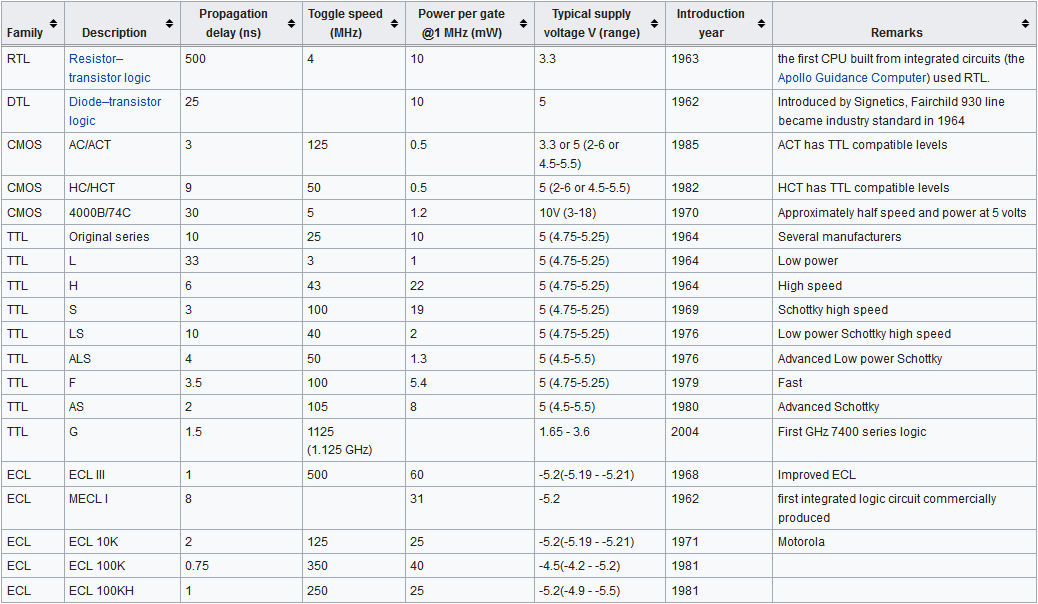
In computer engineering, logic circuit or logic family may refer to one of two related concepts.  A logic family of monolithic digital integrated circuit devices is a group of electronic logic gates constructed using one of several different designs, usually with compatible logic levels and power supply characteristics within a family. Many logic families were produced as individual components, each containing one or a few related basic logical functions, which could be used as "building-blocks" to create systems  or as so-called "glue" to interconnect more complex integrated circuits.

The list of packaged building-block logic families can be divided into categories, listed here in roughly chronological order of introduction, along with their usual abbreviations:
1. Resistor–transistor logic (RTL)
   1.1 Direct-coupled transistor logic (DCTL)
   1.2 Resistor–capacitor–transistor logic (RCTL)
2. Diode–transistor logic (DTL)
   2.1 Complemented transistor diode logic (CTDL)
   2.2 High-threshold logic (HTL)
7. N-type metal–oxide–semiconductor logic (NMOS)
   7.1 Depletion-load NMOS logic
   7.2 High-density nMOS (HMOS)

Logic Circuit

Vibration Resistance - Short essay

Vibration Resistance also know as vibration proofing, is an ability of a device to protect against vibration. Many equipments have high requirements on the physical environment of work, and their performance is susceptible to vibration or even malfunctions and malfunctions. Solid state relays have better vibration resistance than mechanical relays.

Corrosion Resistance - Short essay

Corrosion ResistanceThe ability of metallic materials to resist the corrosive effects of surrounding media is known as corrosion resistance. Solid state relays have better corrosion resistance than mechanical relays.

Mildew Resistance - Short essay

The Mildew Resistance or mold-proof product has the ability to inhibit the growth of mold spores and the growth of mycelium.Solid state relays have better Mildew Resistance than mechanical relays.

Electrical Level - Short essay


Electrical level type
Electrical Level or logic voltage levels. In logic circuits, two voltages are commonly used to represent two logic states, but sometimes two currents are used to represent them. High and low thresholds are specified for each logic circuit. When below the low threshold, the signal is "low". When above the high threshold, the signal is "high". Intermediate levels are undefined, resulting in highly implementation-specific circuit behavior.

Contact Bounce - Short essay

Contact Bounce, or contact chatter,contact jitter usually occurs at the contacts of mechanical relays. When the mechanical contacts are connected or disconnected, due to the elastic action of the mechanical contacts, the mechanical relays will not be turned on steadily when connected, nor will be turned off imitately when disconnected. Therefore, there is a series of jitters at the moment of connecting or disconnecting, ans this phenomenon is contact jitter.

Switching Speed - Short essay

Switching SpeedSwitching speed or switching rate, is the switching  frequency of the mechanical relays and the solid state relays. The higher the switching frequency (or the shorter the switching time), the faster the switching speed.

Mechanical Failure - Short essay

Mechanical failure refers to a significant reduction in the performance of the equipment and is below the minimum required by normal requirements, and is no longer able to maintain normal operation, due to mechanical wear, spark,electric arc,contact jitter and etc. Equipment failures generally include:
   (1) Destructive failures that cause the equipment system to lose functionality immediately.
   (2) Performance failures associated with degrading device system performance.

Mechanical Wear - Short essay

Mechanical WearMechanical wear refers to the friction between the friction surfaces that are in contact with each other to produce relative motion, which will produce the frictional resistance of the movement of the tissue, causing the consumption of mechanical energy and conversion to release heat, causing mechanical wear.

Electro-Magnetic Compatibility - Short essay

Electromagnetic compatibility (EMC) is the branch of electrical engineering concerned with the unintentional generation, propagation and reception of electromagnetic energy which may cause unwanted effects such as electromagnetic interference (EMI), radio frequency interference (RFI) or even physical damage in operational equipment. The goal of EMC is the correct operation of different equipment in a common electromagnetic environment.

Electro-Magnetic Interference - Short essay

Electromagnetic interference (EMI), also called Radio-frequency interference (RFI), is an interference caused by Electromagnetic Radiationgenerated by an interference source to cause malfunction of an electronic device. The electromagnetic interference can cause abnormal operation of the circuit and even directly damage the device.
Types of electromagnetic interference: EMI can be divided into several categories according to the source and signal characteristics. The origin of interference, often called "noise" in this context, can be man-made (artificial) or natural. 

Radio Frequency Interference - Short essay

Radio-frequency interference (RFI), also called Electromagnetic interference (EMI) when in the radio frequency spectrum, is a disturbance generated by an external source that affects an electrical circuit by electromagnetic induction, electrostatic coupling, or conduction. The disturbance may degrade the performance of the circuit or even stop it from functioning. In the case of a data path, these effects can range from an increase in error rate to a total loss of the data.

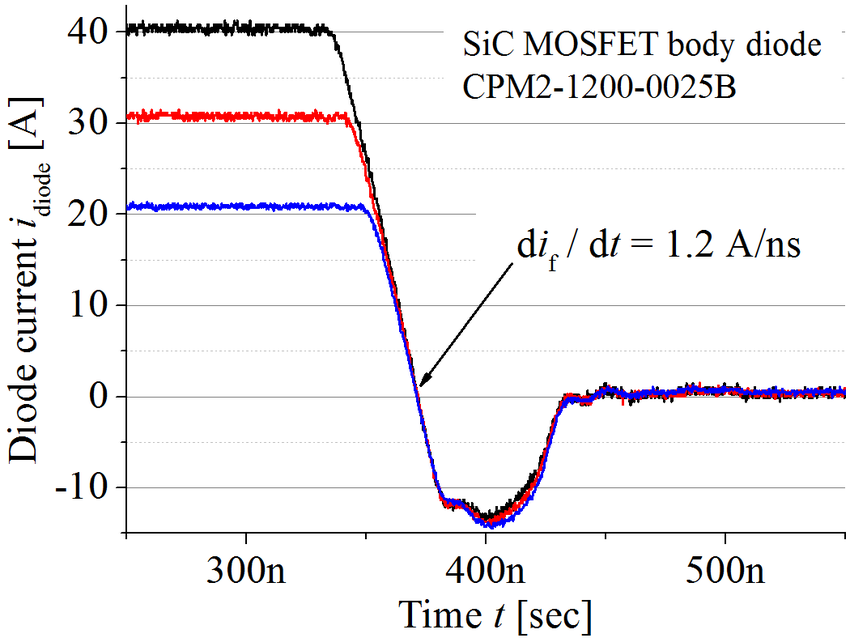
Transistor - Short essay

 A transistor, or triode is a electronic component used to amplify or switch electronic signals and electrical power. It is composed of semiconductor material usually with at least three terminals for connection to an external circuit. A voltage or current applied to one pair of the transistor's terminals controls the current through another pair of terminals. Because the controlled (output) power can be higher than the controlling (input) power, a transistor can amplify a signal. Today, some transistors are packaged individually as discrete Components, but many more are found embedded in integrated circuits.

According to the structure, the transistor can be divided into: BJT, SCR, TRIAC, MOSFET, IGBT, and etc.

According to the electrical polarity (positive and negative), the transistor can be divided into: n–p–n, p–n–p (BJTs); n-channel, p-channel (FETs).

Electromagnetic Relay - Short essay

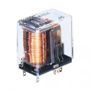
Electromagnetic Relays (also known as traditional mechanical relay, Electromechanical Relay, EMR), are widely used in many fields as the earlist relay. Unlike solid state relays(SSR), electromagnetic relays use mechanical action components with contacts as the switching components (such as Coil-Reed Electromagnetic Relay). When the input terminal of the electromagnetic relay is added with control signals, the coil inside the electromagnetic relay is energized by the input current to generate an electromagnetic field to attract the movable component, so that the movable contact in the movable component contacts with the static contact in the non-movable component to turn on the output circuit of the electromagnetic relay. Mechanical relays are composed entirely of simple mechanical components, so its cost is very low, but these movable parts will generate jitter, sparks , and arcs during operation (which will make contact abnormal and shorten the service life), and also generate electro-magnetic Interference (which will make the input circuit and output circuit unstable). In addition, EMR will be interfered by interference signals, and cannot work in humid environments. Becasue the shortcomings and unreliability performance of electromechanical relays, the solid state relay has gradually replaced the position of the mechanical relay. >>More information about the differences between SSR and EMR>>
Electromagnetic Relay

SPDT Solid State Relay - 3.MGR (HUIMULTD) SPDT SOLID STATE RELAY

§3. MGR (HUIMULTD) SPDT Solid State Relay

3.1 How to select MGR (HUIMULTD) SPDT Solid State Relay

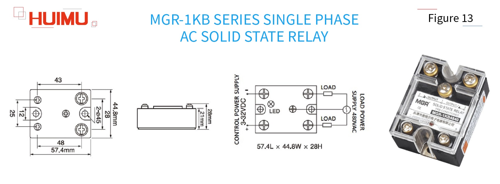
1) MGR-1KB series Single Phase AC Solid State Relay 

Copyright @ huimultd.com

Type meaning:
MGR - 1:[Single phase] - KB:[SPDT (Single Pole, Double Throw)] - 48:[Load voltage 480VAC] - 40:[40A]

Control Voltage:
3~32VDC (such as 3VDC, 5VDC, 9VDC, 12VDC, 18VDC, 24VDC, 32VDC or customized control voltage)
Control Current:
Ultra low input current, ≤20mA
Load Voltage:
Single phase 24~480VAC (such as 24VAC, 48VAC, 110VAC, 230VAC, 380VAC, 480VAC or customized load voltage)
Load Current:
10A, 15A, 20A, 25A, 30A, 40A
Dimensions & Mounting:
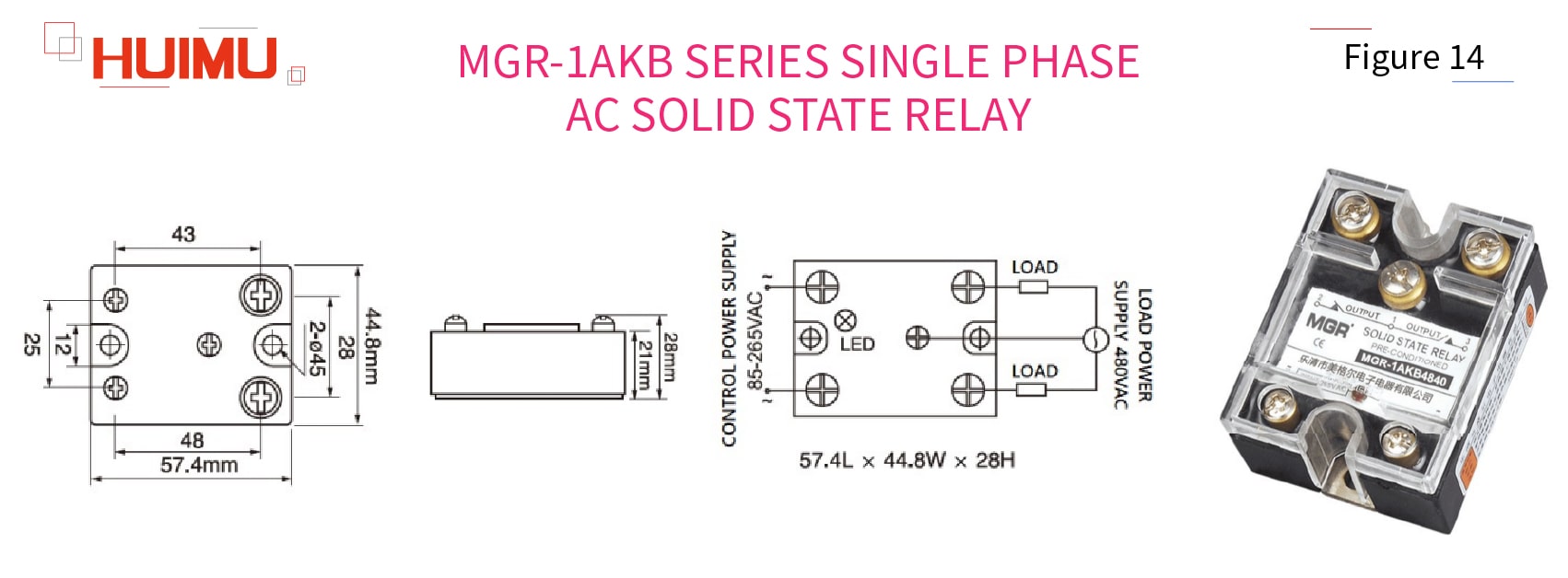
57.4mm*44.8mm*28mm; Panel mount solid state relay with transport cover,metal base and screw terminals

2) MGR-1AKB series Single Phase AC Solid State Relay 

Copyright @ huimultd.com

Type meaning:
MGR - 1:[Single phase] - A:[Control voltage 85-265VAC] - KB:[SPDT (Single Pole, Double Throw)] - 48:[Load voltage 480VAC] - 40:[40A]

Control Voltage:
85~265VAC (such as 100VAC, 110VAC/120VAC, 200VAC, 220VAC/230VAC, 240VAC or customized control voltage)
Control Current:
Ultra low input current, ≤10mA
Load Voltage:
Single phase 24~480VAC (such as 24VAC, 48VAC, 110VAC, 230VAC, 380VAC, 480VAC or customized load voltage)
Load Current:
10A, 15A, 20A, 25A, 30A, 40A
Dimensions & Mounting:
57.4mm*44.8mm*28mm; Panel mount solid state relay with transport cover,metal base and screw terminals

3.2 Why choose MGR (HUIMULTD)

Copyright @ huimultd.com

HUIMU Industrial specializes in providing industrial control products (such as Solid State Relays) and solutions, and consists of two companies: HUIMU Trade and MGR.

MGR is a modern high-tech company integrating R&D, manufacture, sales and service of solid state relays. Since its establishment, MGR has always been adhering to the purpose of " Innovation, Quality, Integrity", and the mission of "Manufacturing the High-Quality Industrial Control Products". For more than 20 years, MGR has continuously innovated and applied for a number of patents, and the MGR brand Solid State Relays are well sold at home and abroad.

MGR's full range of MGR solid state relays are available in a wide range of models and specifications, for example: single/three-phase solid state relay, voltage regulator, power regulator, DC motor governor, three-phase phase-shifting trigger (module), power electronic components (module), and so on. The wide product lines meet the needs of solid state relays in different industries; the high quality makes MGR solid state relays popular in all provinces and cities in China, as well as in Southeast Asia, the Middle East, Europe and the United States, and gains the trust of customers.

The Focus and Passion of technology, has enabled MGR to gather a number of senior engineers and professional technicians. With the joint efforts of the technical team, MGR 's research and development capabilities continue to improve and follow the times, and make it easy to design and develop OEM & ODM customized products according to customer needs.

The Perseverance and Pursuit in quality, make MGR demand itself with international standards. Each operation process strictly follows the IS09001 standard, each part is rigorously tested by superb testing equipment, and the experienced high-quality staff with team spirit is in harmony with advanced production equipment, and the purpose is only for manufacturing high-quality solid state relays.

Copyright @ huimultd.com

SPDT Solid State Relay - 2.WHAT IS SPDT SOLID STATE RELAY

§2. What is SPDT Solid State Relay

Copyright @ huimultd.com

All the switch component (MOSFET, SCR, TRIAC, IGBT, etc.) in the solid state relay only acts as a SPST switch, and there is no single component in the solid state relay that has the SPDT function. Besides, the opto-coupler (with optoelectronic isolation feature) is used in the normal solid state relay as the signal transmission component, so the input control circuit of the SSR switch is electrical insulated to its output circuit. Therefore, if an SPDT solid state relay is required, we can only modify the SPST SSR switch by using a special circuit. And because of the electronic switch components, SPDT solid state relays is more efficient and consumes lower power than SPDT mechanical relays.

The basics of the SPDT SSR switch structure is a little different to the SPDT switch structure:
"Pole" – "Throw (Throw A and Throw B)":
"General-Purpose Push-Pull Outputs (GPout) ①" – "Diodes and Photodiodes";
"Photodiode array ②" – "N-channel enhancement mode MOSFET and N-channel depletion mode MOSFET"
Open: If the pole is disconnected to one throw, the state of this throw is called open state or open.
Close: If the pole is connected to one throw, the state of this throw is called close state or close.
NO (Normally Open): If the throw circuit is disconnected to the pole by default (when the pole is not energized or charged or the voltage level on the pole is zero), this throw circuit will be called the normally open circuit (NO circuit, N/O circuit), and the solid state relay switch will be called normally open SSR switch (NO SSR switch, N/O SSR switch).
NC (Normally Close): If the throw circuit is connected to the pole by default (when the pole is not energized or charged or the voltage level on the pole is zero), this throw circuit will be called the normally closed circuit (NC circuit, N/C circuit), and the solid state relay switch will be called normally closed SSR switch (NC SSR switch, N/C SSR switch).
① Push-Pull Outputs: The push-pull outputs are usually used for two triodes which are controlled by two complementary signals (that is, if one transistor is turned on, the other transistor must be turned off). And the push-pull outputs can output the high voltage level and low voltage level, both of which have the capability to drive the switch components.
② Photodiode array: the stack of photodiodes is used to drive a pair of MOSFETs or an IGBT.

2.1 How does SPDT Solid State Relay work

According to “Pole – Throw”, SPDT solid state relays can be divided into two types: Push-Pull type, and Photodiode-Array type.

1) Push-Pull Type SPDT Solid State Relay

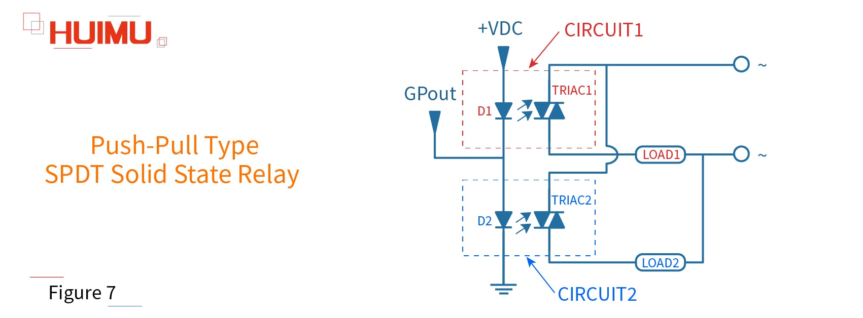
The common circuit diagram of the push-pull SPDT SSR relay as shown below (as shown in Figure 7). The push-pull type SPDT SSR switch consists of two LEDs (D1, D2), and two Photo-TRIACs (TRIAC1, TRIAC2). D1 and TRIAC1 form the CIRCUIT1, and D2 and TRIAC2 form the CIRCUIT2. The push-pull signal (GPout) is generated in the input control terminal of the SPDT SSR, and LOAD1 and LOAD2 is connected to the two output terminals of the SPDT SSR relay.
Copyright @ huimultd.com

According to the GPout signal, there will be three status of the SPDT solid state relay:

1. When a low voltage level is generated in the input terminal, D2 will be turned off, and D1 will be turned on, and TRIAC1 will conduct, then the CIRCUIT1 will be closed, finally the LOAD1 will be switched on.
2. When a high voltage level is generated in the input terminal, D1 will be turned off, and D2 will be turned on, and TRIAC2 will conduct, then the CIRCUIT2 will be closed, finally the LOAD2 will be switched on.
3. If there is no signal on the input terminal, D1 and D2 will be turned off, and CIRCUIT1 and CIRCUIT2 will not be switched on.

Note: Since the GPout outputs and the operating voltage of LED needs to meet certain limits and requirements, the application of Push-pull type SPDT solid state relay is not very extensive.

2) Photodiode-Array Type SPDT Solid State Relay

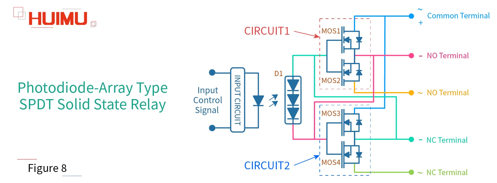
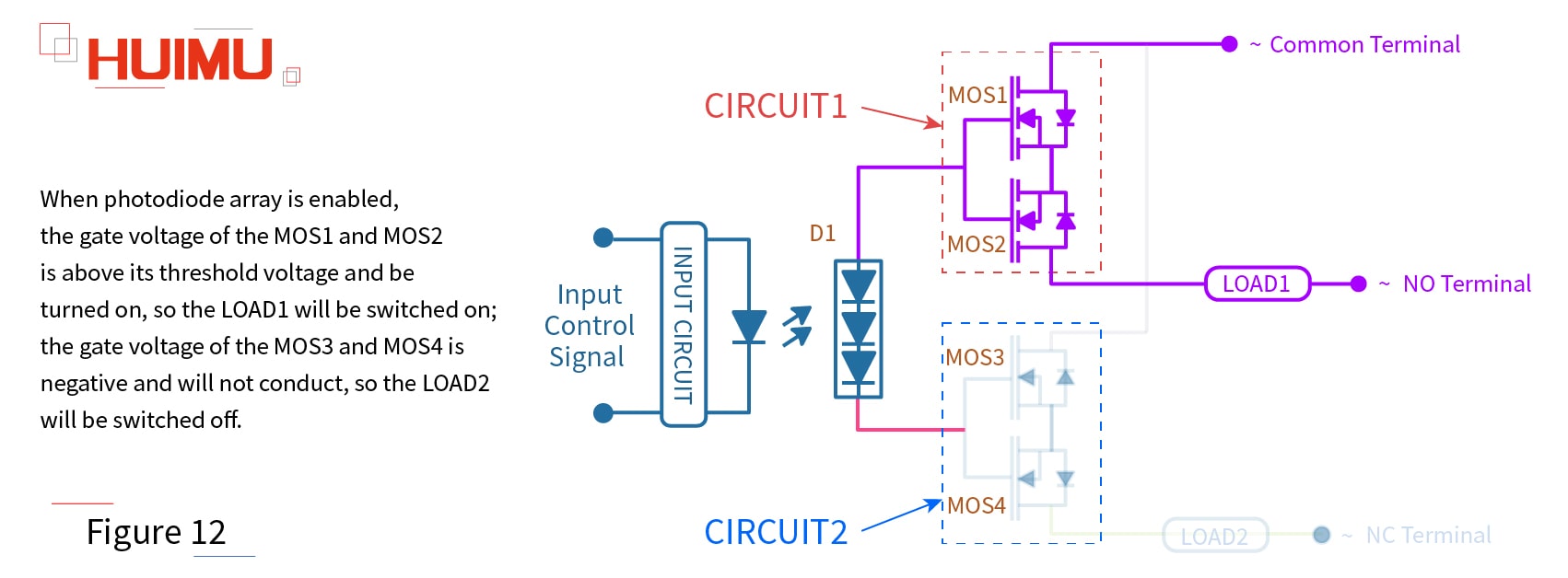
Following shows the common circuit diagram of the photodiode-array SPDT SSR relay (as shown in Figure 8), which can work in DC power supply and AC power supply. The photodiode-array type SPDT SSR switch consists of one photodiode-array (D1), and four N-MOSFETs (MOS1 and MOS2 are enhancement mode N-MOSFETs③; MOS3 and MOS4 are depletion mode N-MOSFETs④). MOS1 and MOS2 form the CIRCUIT1, and MOS3 and MOS4 form the CIRCUIT2. There are 5 output terminals, Port1, Port2, Port3, Port4, Port5, and the Port1 is the common terminal. LOAD1 and LOAD2 is connected to the SPDT switch.
Copyright @ huimultd.com

③ The enhancement mode N-channel MOSFET will turn on when Vgs>Vgs(th)⑤, otherwise it will not conduct.
④ The depletion mode N-channel MOSFET will turn on at zero input, and turn off when its Vgs is negative.
⑤ Vgs is the voltage from gate to source; Vgs(th) is the threshold voltage from gate to source.


1. DC Power Supply
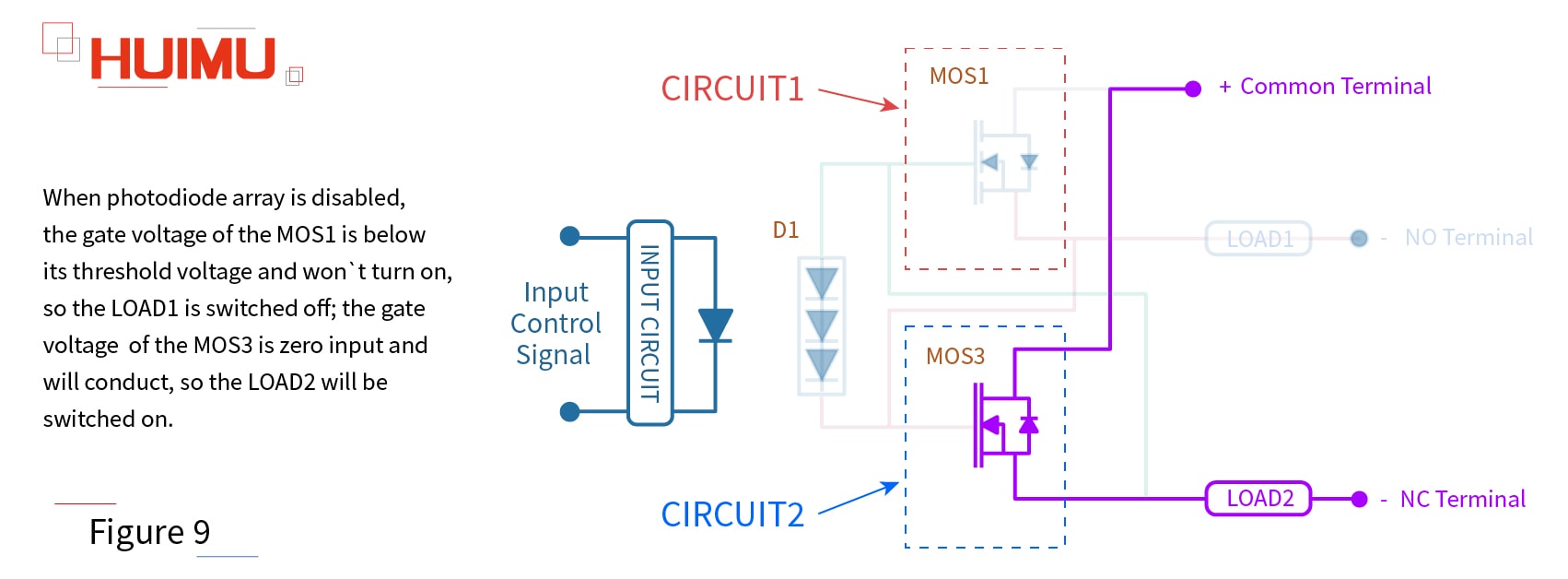
When the photodiode-array SPDT SSR relay is working in a DC power supply, the LOAD1 should be connected to the PORT2, and the LOAD2 should be connected to the PORT4, so the MOS2 and MOS4 will not work.

When photodiode array is disabled, the gate voltage of the MOS1 is below its threshold voltage and won't turn on, so the LOAD1 is switched off; the gate voltage of the MOS3 is zero input and will conduct, so the LOAD2 will be switched on (as shown in Figure 9).
Copyright @ huimultd.com

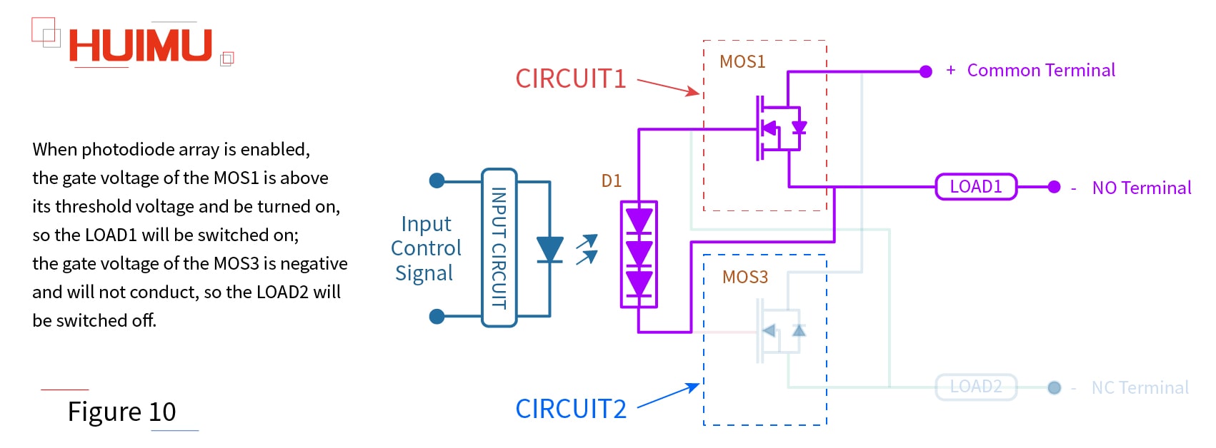
When photodiode array is enabled, the gate voltage of the MOS1 is above its threshold voltage and be turned on, so the LOAD1 will be switched on; the gate voltage of the MOS3 is negative and will not conduct, so the LOAD2 will be switched off (as shown in Figure 10).
Copyright @ huimultd.com

2. AC Power Supply
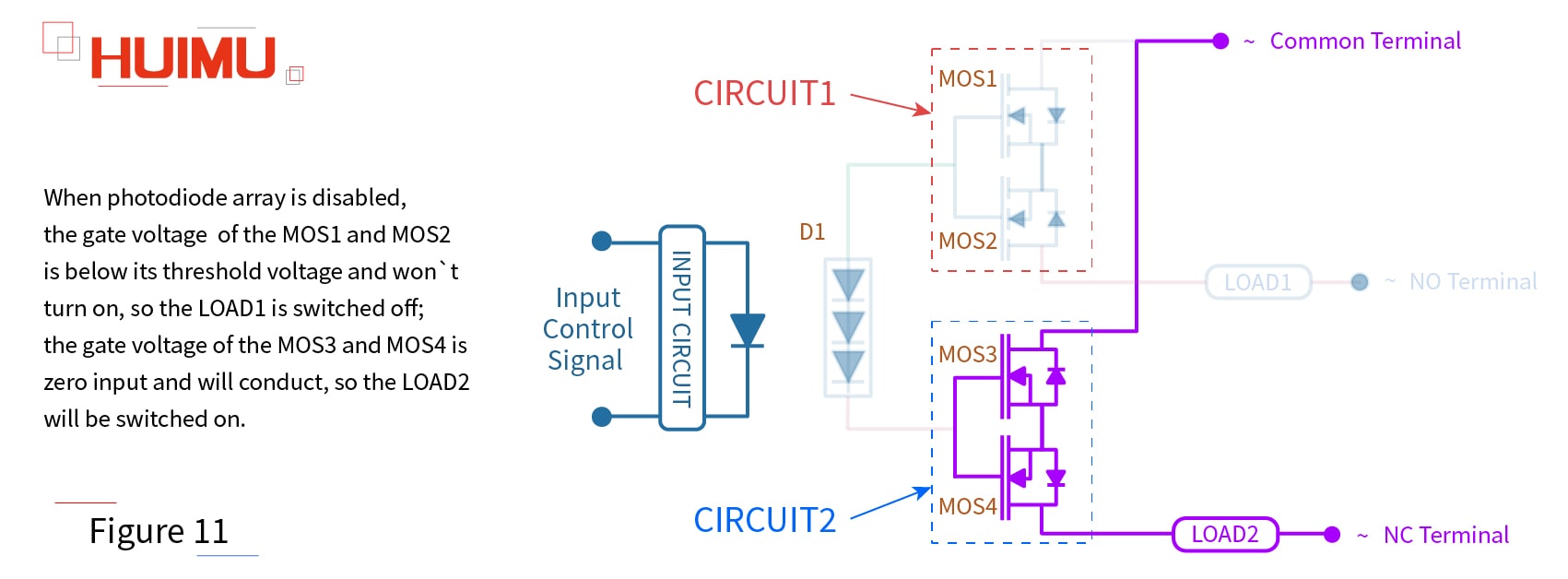
When the photodiode-array SPDT SSR relay is working in an AC power supply, the LOAD1 should be connected to the PORT3, and the LOAD2 should be connected to the PORT5.

When photodiode array is disabled, the gate voltage of the MOS1 and MOS2 is below its threshold voltage and won't turn on, so the LOAD1 is switched off; the gate voltage of the MOS3 and MOS4 is zero input and will conduct, so the LOAD2 will be switched on (as shown in Figure 11).
Copyright @ huimultd.com

When photodiode array is enabled, the gate voltage of the MOS1 and MOS2 is above its threshold voltage and be turned on, so the LOAD1 will be switched on; the gate voltage of the MOS3 and MOS4 is negative and will not conduct, so the LOAD2 will be switched off (as shown in Figure 12).
Copyright @ huimultd.com

Note: Because of the features of N channel enhancement MOSFETs and N channel depletion MOSFETs, this kind of solid state relays are widely used to control the DC load circuit and the AC load circuit.

2.2 What is SPDT solid state relay used for

Solar Battery Charger

SPDT solid state relays are typically used in solar power charger systems (such as portable solar charger) to control the solar cell charging equipment. The working state (charging state and power state) of the solar cells is switched much frequently, so the SPDT mechanical relays cannot meet this requirement, but the SPDT SSRs can.

Soft Starter System

When the electronic/electrical systems (and their subsystems) works normally, the switching frequency of its soft start state and stop state is very high. Therefore, the SPDT make-before-break switch need to be equipped to prevent overvoltage when switching.

Remote Control Device / Radio Transmitter

If the remote control device wants to control multiple objects, it needs to change the transmitted signal; if the communication tower wants to switch the recipient, it needs to change the transmission signal. This kind of equipment require strict operating frequency and operation accuracy, and SPDT solid state relays can meet these requirements in most cases.

Satellite Heater

In the space environment, there are high requirements (weight, anti-interference ability, adaptability, and so on) to every device. The SPDT solid-state relay (with lots of advantages, like small weight, high performance, long service life, low power consumption, low EMR and etc.) meet these requirements, and is much better than the SPDT electromechanical relay (simple structure, but high weight, poor anti-interference ability and cannot adapt to complicated situations due to overweight).
SPDT Solid State Relay - 1.WHAT IS SPDT SWITCH

§1. What is SPDT Switch

Copyright @ huimultd.com

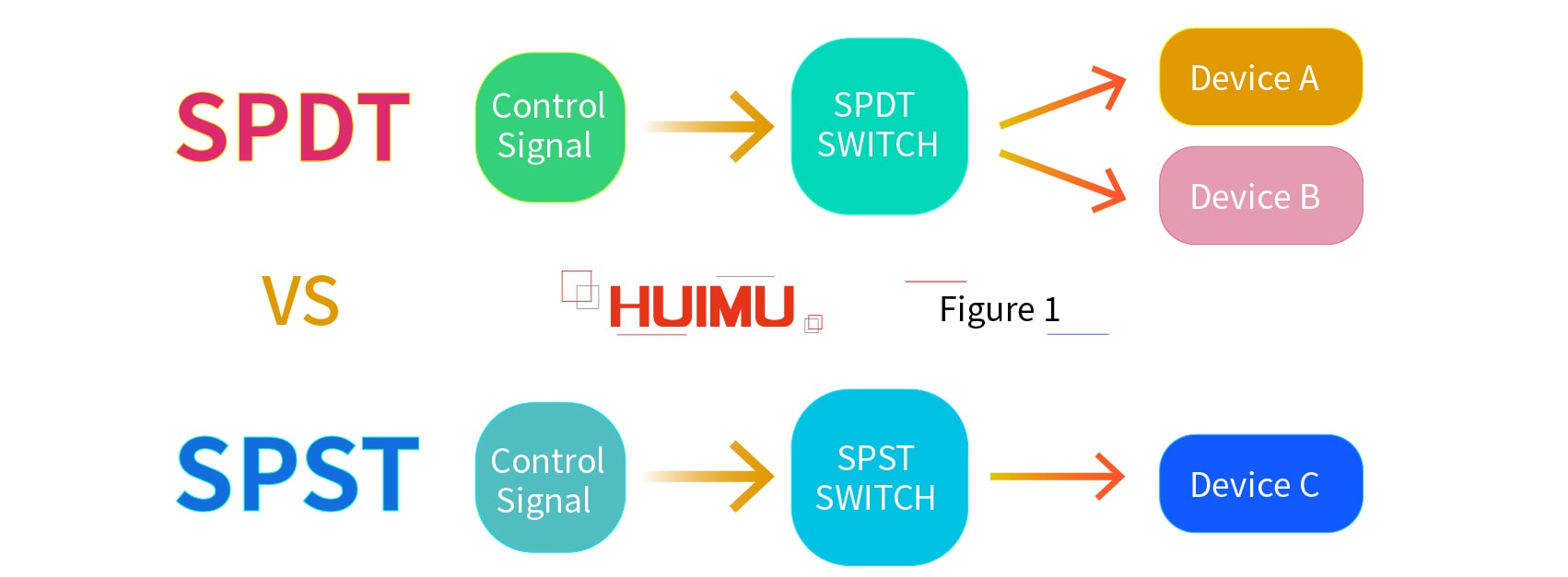
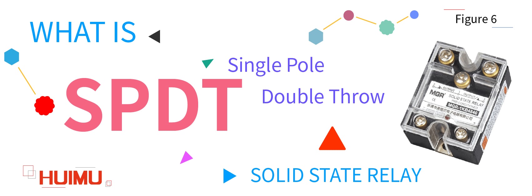
SPDT (Single Pole Double Throw) is a special switch structure. Different with the normal SPST (Single Pole Single Throw) switches, SPDT switches control the working status of two devices, and these two devices work in opposite status. For example, a SPDT switch is connected to Device A and Device B, the Device A will be on status and the Device B is shut down if the SPDT switch is switched off; conversely, if the SPDT switch is switched on, the Device A will be off status and the Device B will be turned on. Therefore, we can know that no matter what state the SPDT switch works on, only one device will be turned on.

1.1 What is the Structure of SPDT Switch

Copyright @ huimultd.com

The basics of the SPDT switch structure:
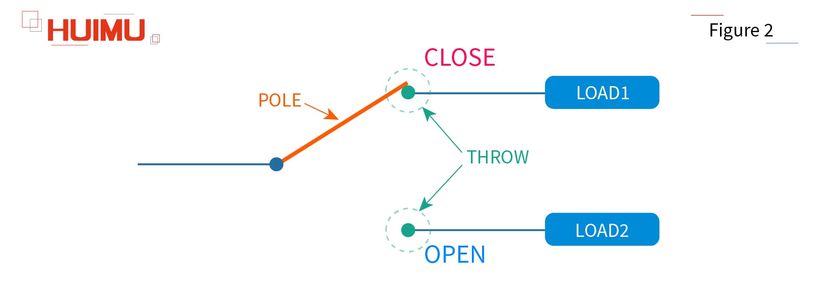
Pole: The pole is the controller inside the switch. We usually use single pole, double pole, or etc. to show how many separate circuits that controlled by the switch.
Throw: The throw means the circuit that will be controlled by the pole. We usually use single throw, double throw, or etc. to show how many circuits will be controlled by one Pole.
Open: If the pole is disconnected to one throw, the state of this throw is called open state or open.
Close: If the pole is connected to one throw, the state of this throw is called close state or close.
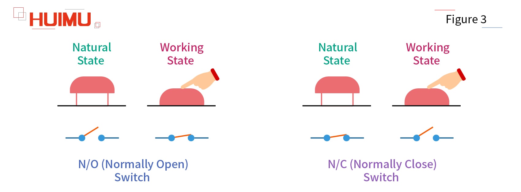
NO (Normally Open): If the throw circuit is disconnected to the pole by default (when the pole is not subject to any external forces), this throw circuit will be called the normally open circuit (NO circuit, N/O circuit), and the switch will be called normally open switch (NO switch, N/O switch).
NC (Normally Close): If the throw circuit is connected to the pole by default (when the pole is not subject to any external forces), this throw circuit will be called the normally closed circuit (NC circuit, N/C circuit), and the switch will be called normally closed switch (NC switch, N/C switch).

Copyright @ huimultd.com

SPDT switch is a five terminal switch device — two input terminals, and three output terminals (two terminals connect to the load, and one terminal connect to the common terminal). And if one of SPDT switch output terminals does not connect to any circuit (which means only one control circuit and one output circuit are connected to the SPDT switch), the SPDT switch functions as a SPST switch.

Generally, the SPDT switch will be more suitable and efficient for some special applications than what two normal SPST switches (which need two control circuits) can do, like switching two different power supplies in opposite status, or activating two circuits with different functions in opposite status.

1.2 How does SPDT Switch work

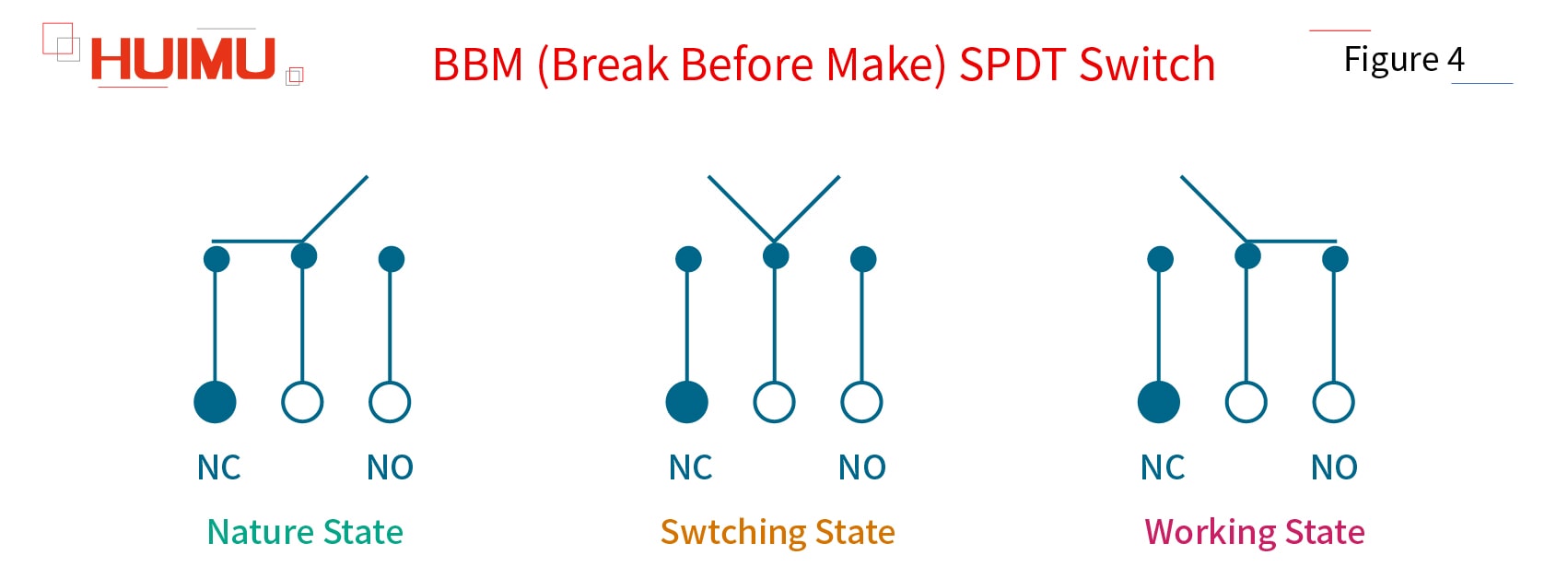
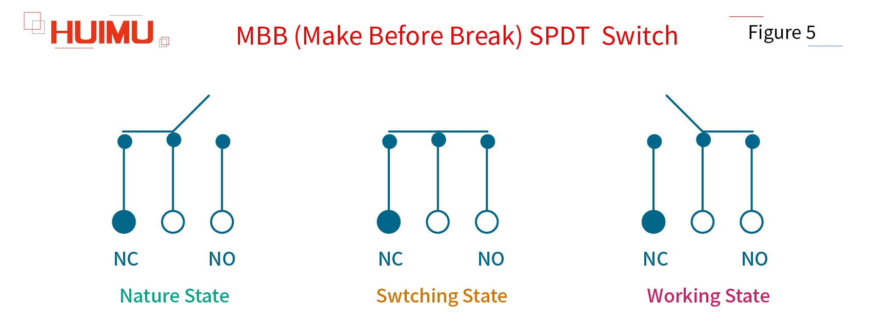
According to the way of operating, the single pole double throw switch can be divided into BBM type SPDT switch (break-before-make) and MBB type SPDT switch (make-before-break).

1) BBM (Break Before Make) SPDT Switch

By default, the pole of the BBM SPDT switch is connected to NC throw circuit and disconnected from the NO throw circuit. When the break-before-make switch is switched, it will first disconnect to the NC circuit, and then connect to the NO circuit.

Copyright @ huimultd.com

2) MBB (Make Before Break) SPDT Switch

By default, the pole of the MBB SPDT switch is connected to NC throw circuit and disconnected from the NO throw circuit. When the make-before-break switch is switched, it will first connect to the NO circuit, and then disconnect to the NC circuit.

Copyright @ huimultd.com

How To Order SSR

How to select (order) solid state relays (SSR), solid state modules (SSM), and heat sink? More detail via www.@huimultd.com

The PDF file below shows the full range of solid state relay series, module series and heat sink series produced by MGR, which can be viewed online or downloaded locally for convenient selection.


How to select a suitable heat sink for solid state relays and solid state modules?

§1. How the Heat Sink works

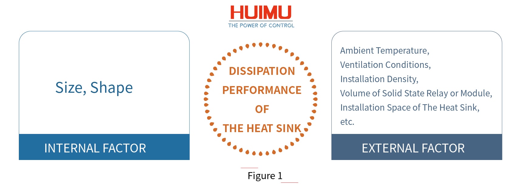
The role of the heat sink is to dissipate the heat generated by the solid state relay or module to ensure that the solid state relay or module will work stably and reliable at optimum conditions and not be burned and damaged due to high temperatures. The heat dissipation effect of the heat sink is not only related to its specification (size, shape), but also related to external environmental factors, such as the ambient temperature (season), ventilation conditions (natural cooling or forced cooling, and ventilation volume), and installation density. In addition, it is also necessary to consider whether the volume of the solid state relay or the module itself and the installation space of the heat sink in the equipment matches the specifications of the heat sink.

Copyright @ huimultd.com

The cooling method of the solid state relay/module can be divided into Air Cooling method and Water Cooling method. And the air cooling heat sink can be farther divided into the Heat Sink (natural cooling) and Air Cooled Radiator (forced cooling by fan). Normally, if the load current of the solid state relay/module reaches 10A, a heat sink must be equipped; if the load current is 40A or more, an air-cooled radiator or a water-cooled radiator must be installed. When the module is used for the load with load power greater than 15 KW, it is recommended to use a suitable heat sink, and apply thermal grease between the heat sink and the SCR backplane, as well as cold air to cool down. If the current is below 350A, the module is cooled by forced air cooling; if the current is more than 400A, the cooling method for the module can be either air-cooling or water-cooling.

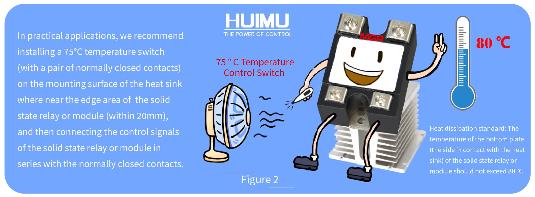
Heat dissipation reference standard: The temperature of the bottom plate (the side in contact with the heat sink) of the solid state relay or module does not exceed 80 °C.

Copyright @ huimultd.com

In practical applications, we recommend installing a 75°C temperature switch (with a pair of normally closed contacts) on the mounting surface of the heat sink where near the edge area of the solid state relay or module (within 20mm), and then connecting the control signals of the solid state relay or module in series with the normally closed contacts. In this way, when the temperature of the detection point exceeds 75 °C, the normally closed contact will trip and cut off the control signal, and the output terminal of the solid state relay or module will be forcibly turned off to get protection. Generally, if the solid state relay or module is installed to the place with the actual current of each phase exceeding 50A, the high installation density and ambient temperature, it is better to apply a temperature switch for protection to ensure that the temperature of the bottom plate of the solid state relay or module does not exceed 80 ° C under severe conditions.

§2. How to calculate the Heat

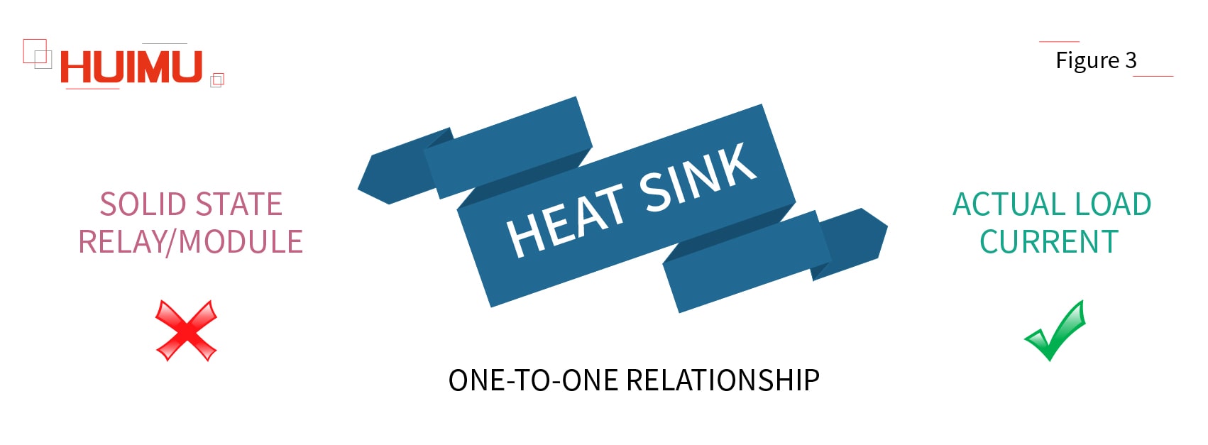
At first, we should know that there is no one-to-one correspondence between the model (type) of the heat sink and the model (type) of the solid state relay or module. Since solid-state relays use transistors as electronic switching components/power components, the heat generated by the solid state relay or module is mainly related to the actual current of the load it drives, instead of its own rated current specification (current grade).

Copyright @ huimultd.com

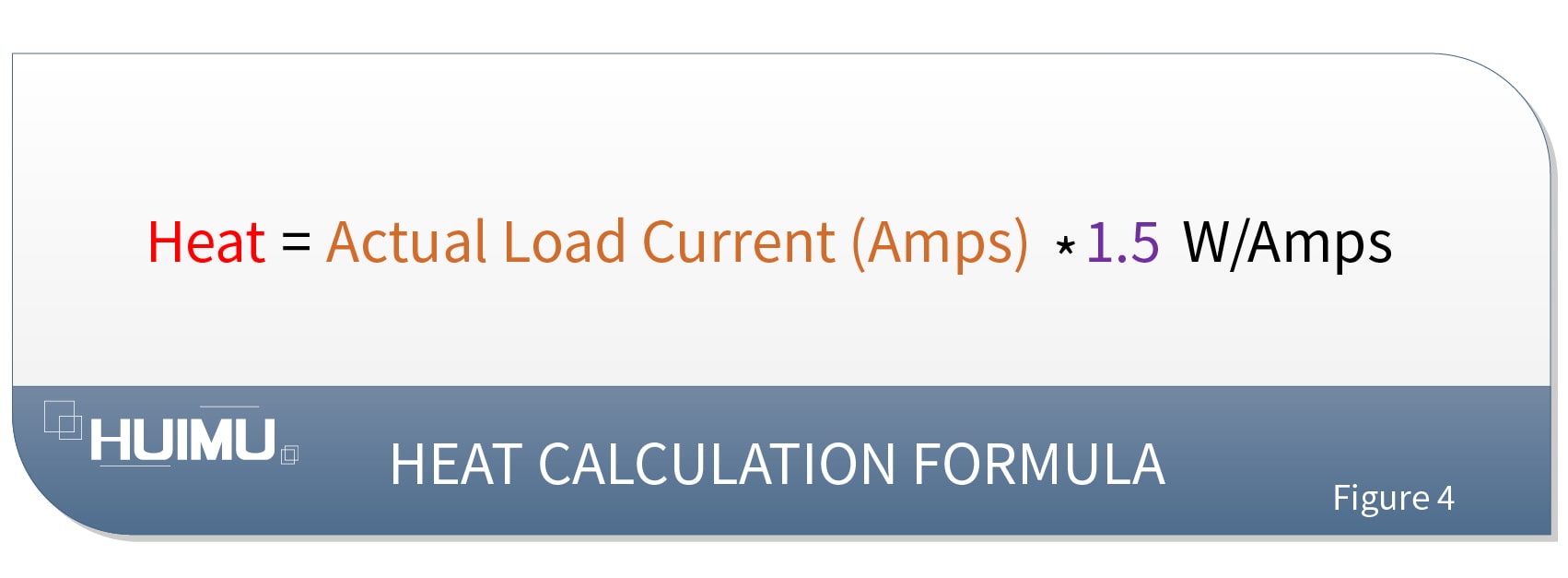
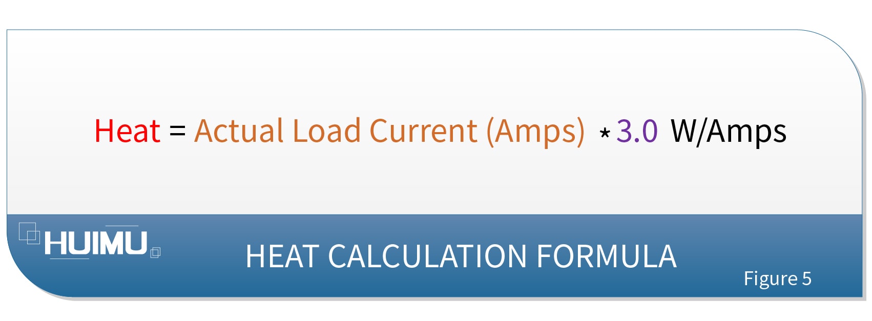
The heat generated by the solid state relay/module in practical applications can be calculated by the following formula:

1. Heat = Actual Load Current (Amps) * 1.5 W/Amps

Copyright @ huimultd.com

Note: The above formula is suitable for single phase solid state relays, single phase AC voltage regulator modules, and R series solid state voltage regulators. For three phase solid state relays and three phase AC voltage regulator modules, the actual load current should be the sum of the actual load currents.

2. Heat = Actual Load Current (Amps) * 3.0 W/Amps

Copyright @ huimultd.com

Note: The above formula is suitable for single phase fully-controlled bridge rectifier module.

§3. How to select Heat Sink / Radiator

Copyright @ huimultd.com

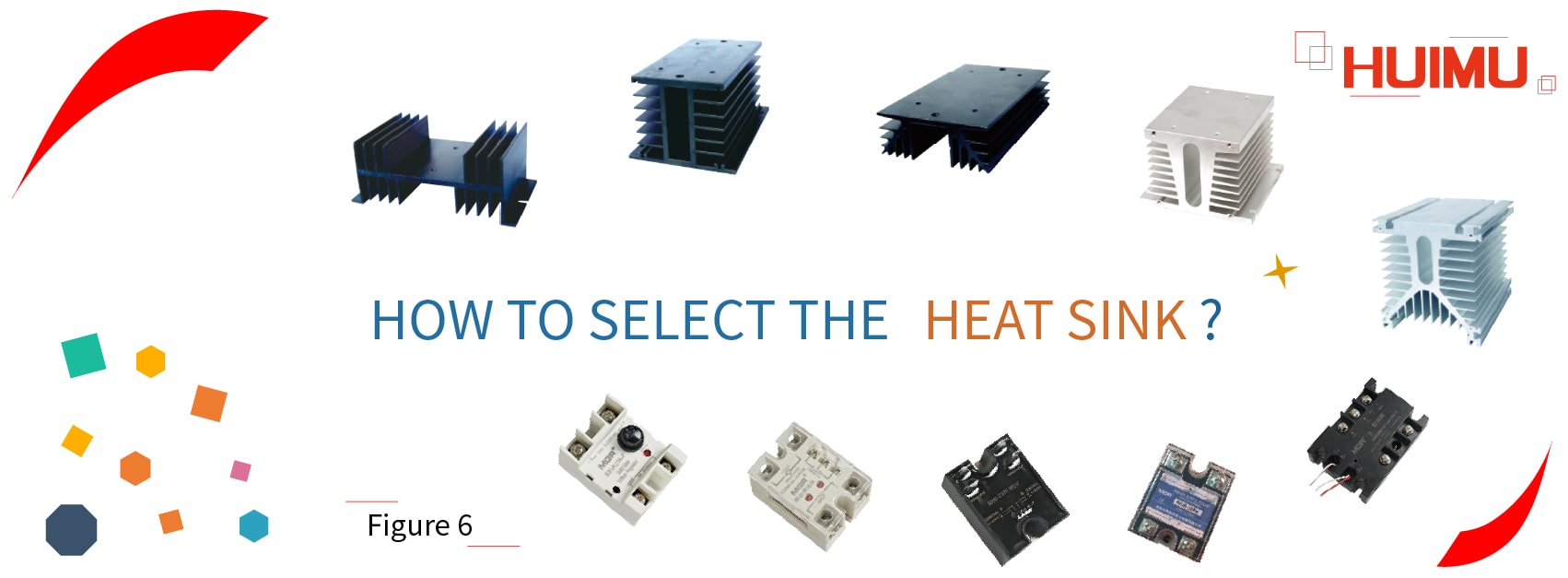
MGR (HUIMULTD) Heat Sink / Radiator  series
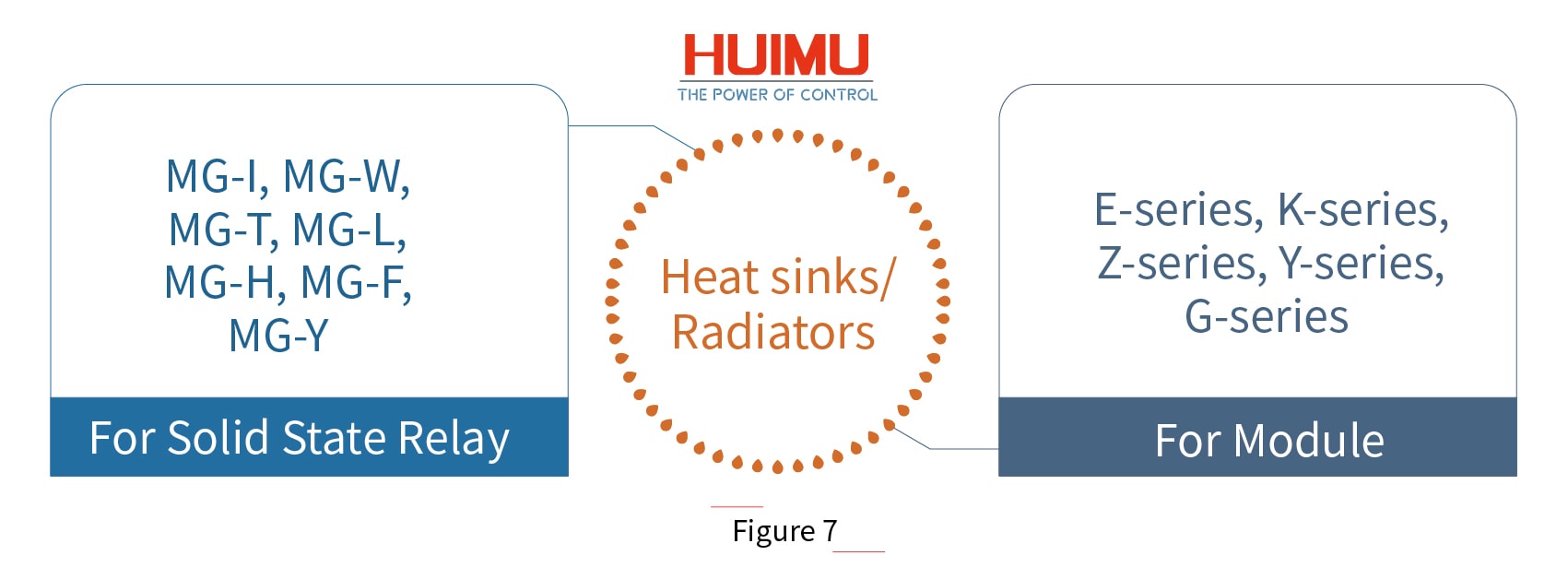
The heat sinks/ radiators produced by our company are divided into two categories, for solid state relay and for module.

◆ For Solid State Relay: MG-I, MG-W, MG-T, MG-L, MG-H, MG-F, MG-Y.

These seven series are suitable for a variety of single phase solid state relays, single phase AC voltage regulator modules, R series solid state voltage regulators, industrial solid state relays and various three phase AC solid state relays, etc.

◆ For Module: E series, K series, Z series, Y series, G series.

These series are usually used with an air-cooled fan, suitable for DC commutator modules, voltage regulator modules, rectifier modules, phase-shift trigger modules, thyristor modules, hybrid modules, welding machine modules, etc.

Copyright @ huimultd.com

The following are the general applications and selection of some radiators:

MGR-DT Series Full Isolation Single Phase AC Solid State Voltage Regulator Module
The heat of the whole module = Actual load current (Amps) * 1.5 W/Amps. Customers can select MG-L, MG-H series heat sink according to actual needs.

MGR-DQZ Series Single Phase Full Isolation Fully-Controlled Solid State Bridge Rectifier Module
The heat of the whole module = Actual load current (Amps) * 3.0 W/Amps. Customers can select MG-L, MG-H series heat sink according to actual needs.

MGR-STY Series Full Isolation Three Phase AC Voltage Solid State Voltage Regulator Module
The heat of the whole module = Actual load current (Amps) * 1.5 W/Amps. Customers can select MG-Y, MG-H series heat sink according to actual needs.

SSR-3JK Series Three Phase Solid State Phase-Shift Trigger Module (For Solid State Relays)
SSR-3JK and TB-3 generate very little heat and do not need to be mounted on a heat sink.

The SSR-3JK (with TB-3) matches the random solid state relays produced by our company. Users can build the SSR-3JK system by purchasing the SSR-3JK, the TB-3, three random conduction type SSRs and one heat sink to. If three long strip solid state relays are selected, they can be mounted on a Y series module air-cooled radiator with a fan installed to form a power unit; and if three rectangular solid state relays are selected, they can be mounted on the MG-Y heat sink to form a power unit.

SX-JK Series Three Phase Solid State Phase-Shift Trigger Module (For Thyristor Circuits)
SX-JKA, SX-JKT, SX-JKZ, SX-JKB, TB-3A, and TB-3Z generate very little heat and do not need to be mounted on a heat sink.

Copyright @ huimultd.com

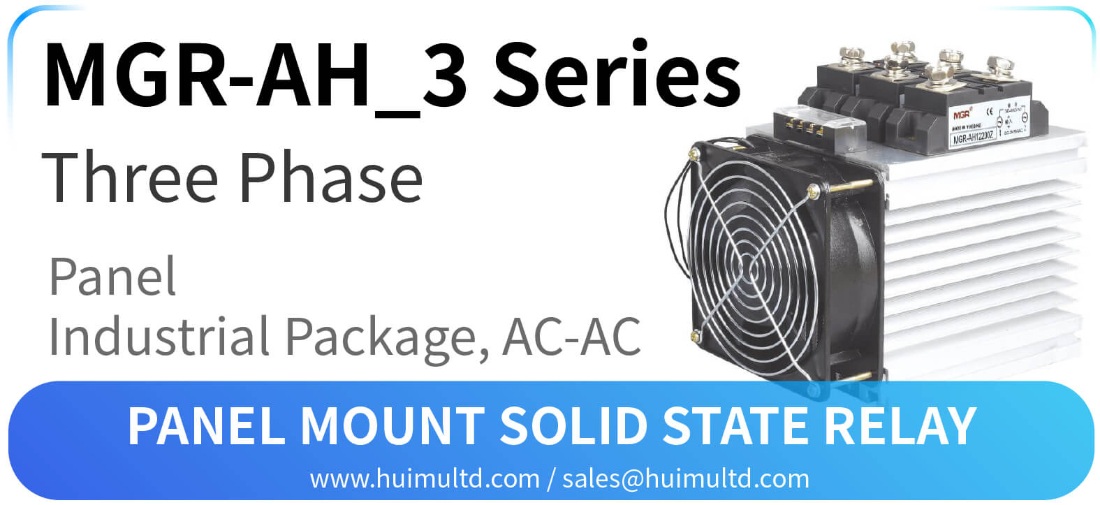
MGR-AH_3 Series Panel Mount Solid State Relay

  MGR-AH_3 Series Panel Mount Solid State Relay [All the information on this website is for reference only, and the actual product and the a...