§9. Attentions when using or installing Solid State Relays
1) The actual application conditions of the product must fully comply with the requirements of the parameters and characteristic curves of solid-state relays.
2) SSR should not be used in applications with a large number of low or high harmonic components (for example, multiple sets of loads at the output of the inverter need to be switched separately). If the solid state relay is used in inverter as an electronic switch, because of the higher harmonics, the solid state relays may not be able to switch reliably, and the RC circuit inside the SSR relays will be exploded due to overheating.
3) The SSR relays should be kept away from strong electromagnetic interference sources and RF interference sources to ensure that the SSR can operate stably and safely, avoiding loss of control.
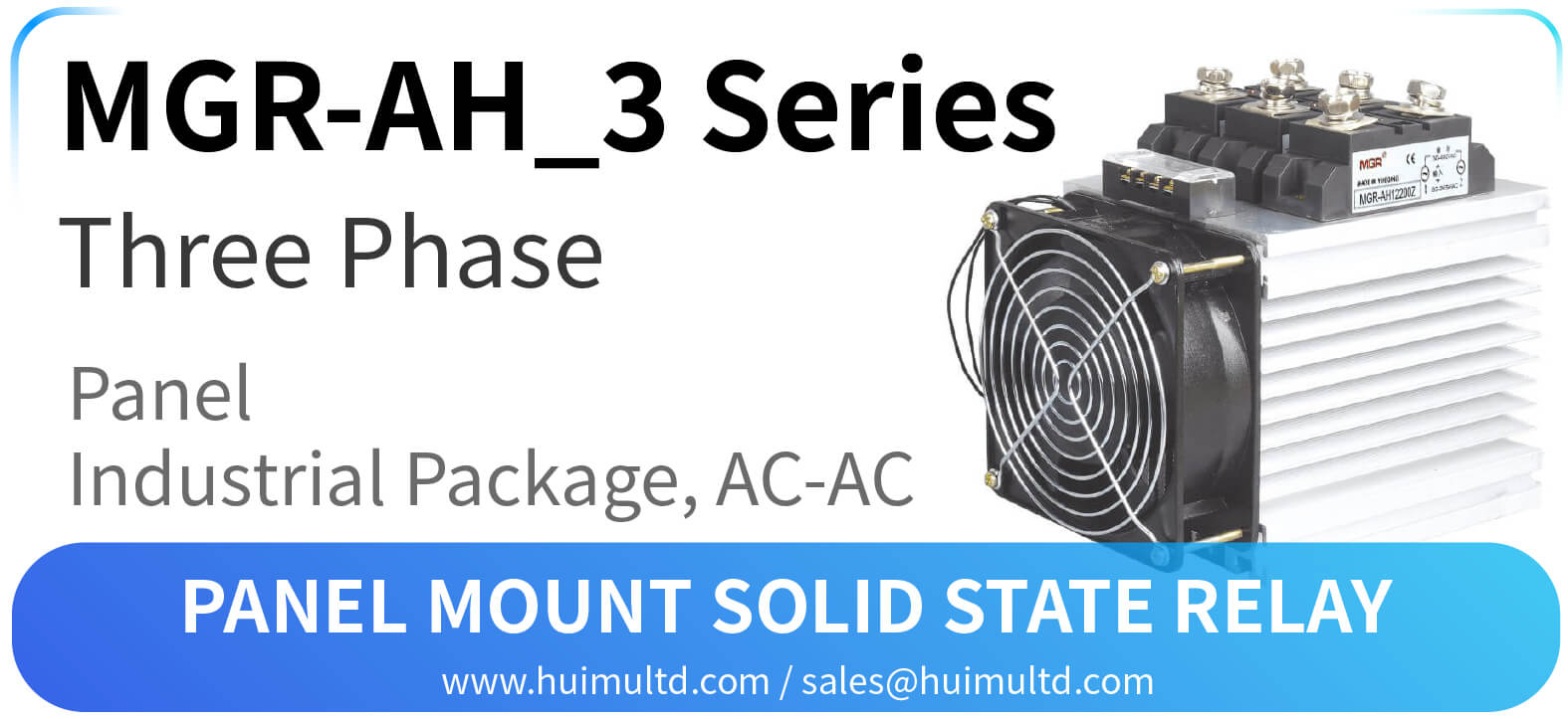
4) Except for the solid state relay with rated current of 1~5A which can be directly mounted on the printed circuit board, the other solid-state relays should be equipped with appropriate heat sinks. Thermal grease should be applied between the SSR base plate and the heat sink, and screwed tightly to make them close to each other for optimum heat dissipation. Or install a temperature control switch near the SSR relays backplane and the temperature control point is typically set between 75 °C and 80 °C.
5) When the input voltage of the input control signal is too high and exceeds the rated parameter of the SSR, the input resistor can be connected in series to the input circuit to reduce the excess value. Similarly, when the input current is too large, the shunt resistor can be connected in parallel to the input port.
6) The control signal and the load power supply need to be stable, and the fluctuation should not exceed 10%, otherwise the voltage regulation measures should be taken.
7) If using solid state relay to control the primary circuit of the transformer, the influence of the transient voltage of the secondary circuit on the primary circuit should be considered. In addition, since the current is asymmetrical in both directions, the transformer may also generate surge currents caused by saturation. In this case, the oscilloscope can be used to measure the inrush current and voltage that can be caused, so that the appropriate SSR and protection measures can be selected.
8) The output of the solid state relay is not completely isolated, when load power is applied to the output terminals, even if the solid-state relay does not operate, there will be some leakage current at the output terminals, which should be noted when using and designing the circuit. During maintenance, the service personnel must cut off the power supplies before checking the output circuit.
9) When a solid state relay needs to be replaced due to a fault, the SSR relay with the same model or technical parameters is recommended, to match the original application circuit and ensure reliable operation of the system.
