§8. How to select the Solid State Relays
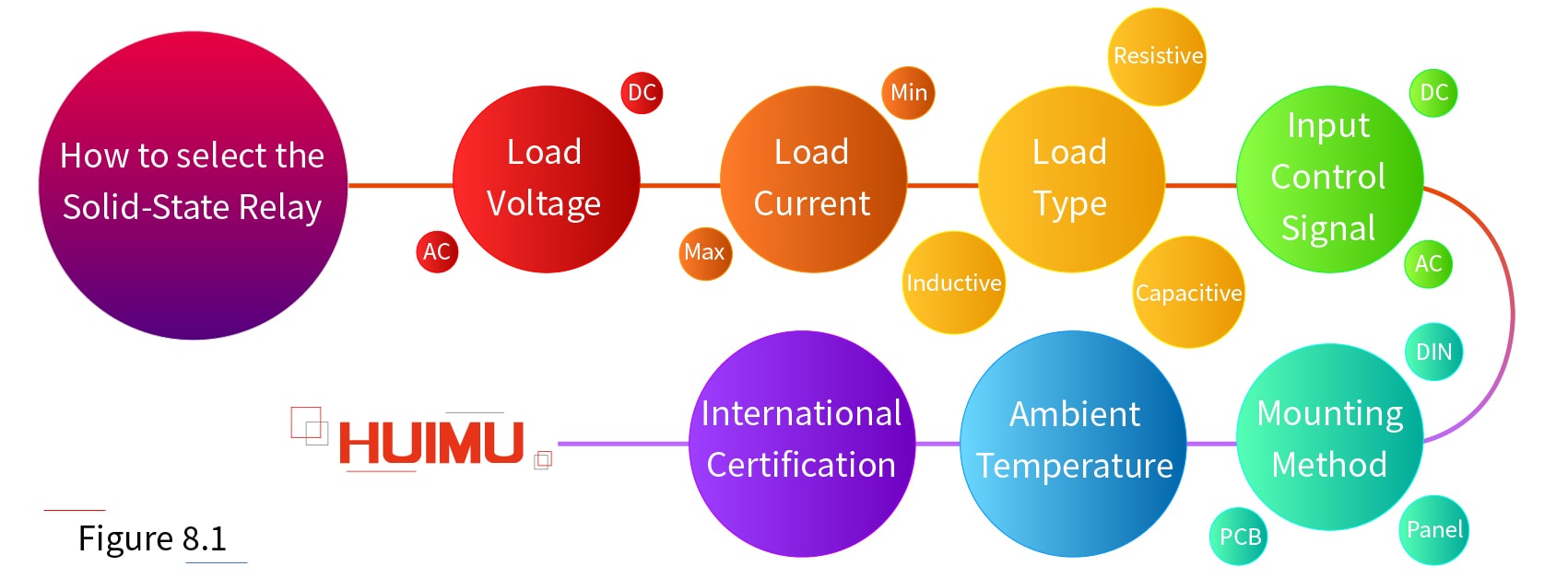
The following are options to consider when selecting the appropriate solid-state relays based on the actual requirements:
1) Load Voltage - AC or DC
2) Load Current - Maximum Current and Minimum Current
3) Load Type - resistive, inductive or capacitive
4) Input Control Signal - AC or DC
5) Mounting Method - PCB, Panel or DIN rail mounting
6) Ambient Temperature - for calculating the Derating Factor and the size of the heat sink
7) International Certification – Underwriter Laboratories (UL), Canadian Standards Association (CSA), British Approvals Board of Telecommunications (BABT), Verband Deutscher Elektrotechniker (VDE), Technischen Uberwachungs Vereine (TUV), Conformite Europeene (CE) or other.
Load Voltage:
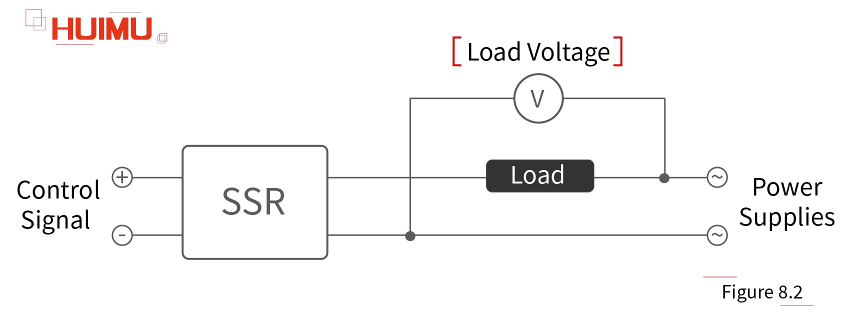
The first consideration is whether the load voltage is AC or DC to determine whether AC-SSR or DC-SSR is selected. Secondly, the voltage of the load power supply should be considered which cannot be larger than the output rating voltage, and less than the minimum voltage of the solid-state relay. Then consider the magnitude of the load voltage and the transient voltage. The load voltage refers to the steady-state voltage applied to the SSR switch output terminal, and the transient voltage refers to the maximum voltage that the output terminals of the SSR relays can withstand. When the AC inductive load, single-phase motor load or three-phase motor load is switched or energized, the voltage at the SSR switch output may be twice the peak voltage of the power supply, and this voltage cannot be greater than the transient voltage of the SSR to prevent the excessive shock voltage from damaging the electronic switch. Therefore, when selecting the SSR, it is best to leave a margin for the output voltage, and select the SSR relay with RC Circuit to protect the solid-state relay and optimize dv / dt.
RC Circuit:
RC circuit, also known as RC filter, RC snubber, or RC network, is a circuit consisting of the resistor and the capacitor. It is recommended to select solid state relays with a varistor absorption circuit and an RC snubber circuit. The RC circuit blocks certain frequencies from passing and allows other frequency signals to pass to filter out the interfering signals. Moreover, the RC circuit can also be used to reduce the rise rate of the output voltage (dv/dt), to absorb the surge voltage, suppress excessive transient voltage / current, and prevent the solid-state relay from being broken due to overvoltage.
Load Current:
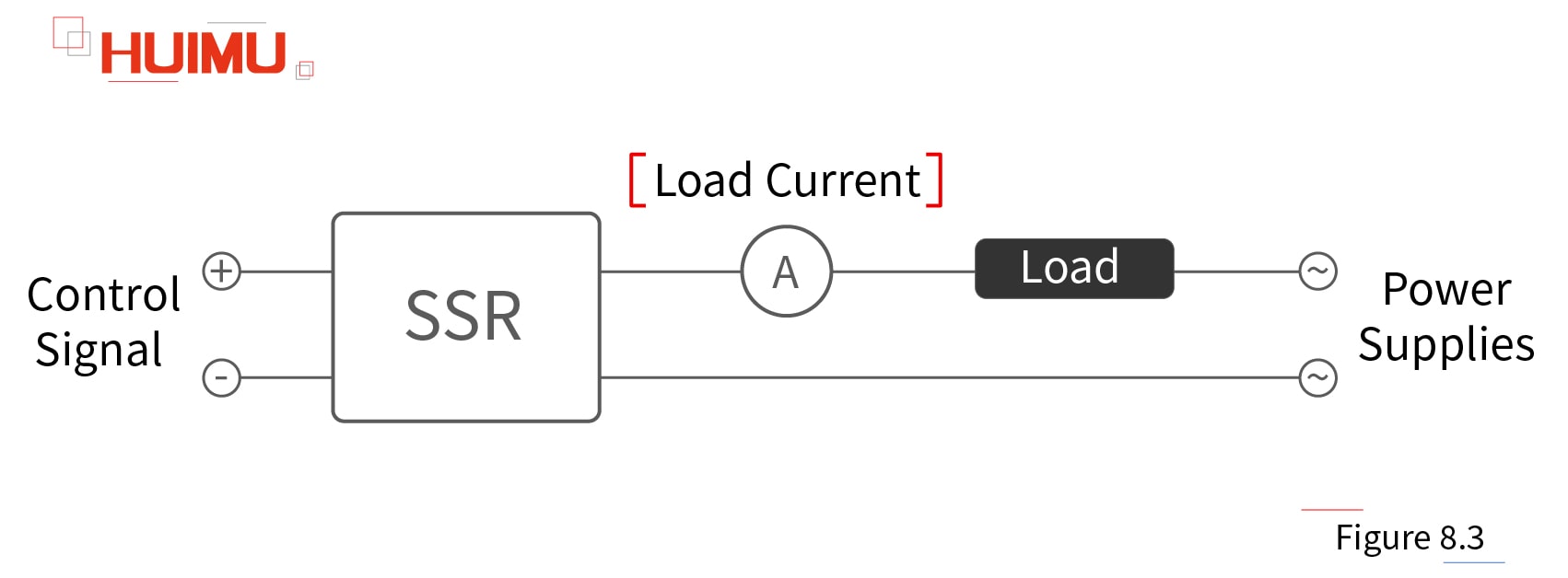
The output current value of the solid state relay is the steady-state current flowing through the output terminals of SSR, which is usually equal to the current of the load connected to the SSR output terminal. Since the switching elements of the SSR switches are very sensitive to temperature, and the overcurrent can generate a high amount of heat, so the overload capability of the SSR is weak. Therefore, the output current of the SSR relay shall not exceed its rated output current, and the surge current shall not exceed the overload capacity, especially for inductive/capacitive loads that are prone to generate surge currents, as well as the inrush current generated by the power supply itself.
The output current requires a margin to avoid excessive inrush currents that reduce the life of the solid-state relay. For general resistive loads, the rated effective operating current value can be selected based on 60% of the nominal value. Besides, the fast fuse and the air switch could be considered to protect the output loop, or add an RC sink loop and a varistor (MOV) to the output of the relay. The selection specification of varistor is to select 500V~600V MOV for 220VAC SSR, and 800V~900V MOV for 380VAC SSR.
Inrush Current:
Almost all the controlled loads will generate large inrush currents at the moment of turn-on. For example:
1) The electric heating devices, like the incandescent lamps, and the electric furnaces, etc. They are purely resistive loads with a positive stability coefficient, but the resistance is small at a low temperature, so the current at startup will exceed several times the steady state current.
2) Some types of lamps have low impedance when burned off.
3) When the motor is turned on, rotor locked, and turned-off, it will generate large inrush current and voltage. The locked-rotor is a situation in which the motor still outputs torque when the speed is 0 rpm, at the meantime, the power factor of the motor will be extremely low, and the current can be up to 7 times of the rated current.
4) When the intermediate relay or solenoid valve is not closed reliably and bounce, it will also generate large inrush current.
5) When the capacitor bank or capacitor power supply are switched, there will cause a similar short circuit condition, and generate very large current.
6) When the capacitor commutated type motor is reversing, the capacitor voltage and the supply voltage are superimposed on output terminal of the SSR, and SSR will withstand a surge voltage twice the supply voltage.
Excessive inrush current can damage the semiconductor switches inside the SSR. Therefore, when selecting a relay, the surge characteristics of the controlled load should be analyzed first, so that the relay can withstand the inrush current while ensuring steady-state operation. The rated current of solid state relay should be selected according to the derating factor in actual requirements. And if the selected relay needs to work in a place with frequent operation, long life and high reliability, the rated current should be divided by 0.6 based on the known derating factor, to ensure the reliability of operation. Additionally, the resistor or inductor can be connected in series to the output loop to further limit the current.
Attention: Please do not use the SSR surge current value as the basis for selecting the load starting current. Because the SSR relay surge current value is based on the surge current of electronic switch with the precondition of half (or one) power supply cycle, that is 10ms or 20ms.
Load Type:
The loads can be divided into three types based on the electrical impedance: Resistive Load Type (or Pure Resistive Load), Inductive Load Type and Capacitive Load Type. There is no pure inductive load and pure capacitive load in the usual electrical appliances, because these two type loads don not do active power. In the series-parallel circuit, if the capacitive reactance is larger than the inductive reactance, the circuit is capacitive load; and vice versa.
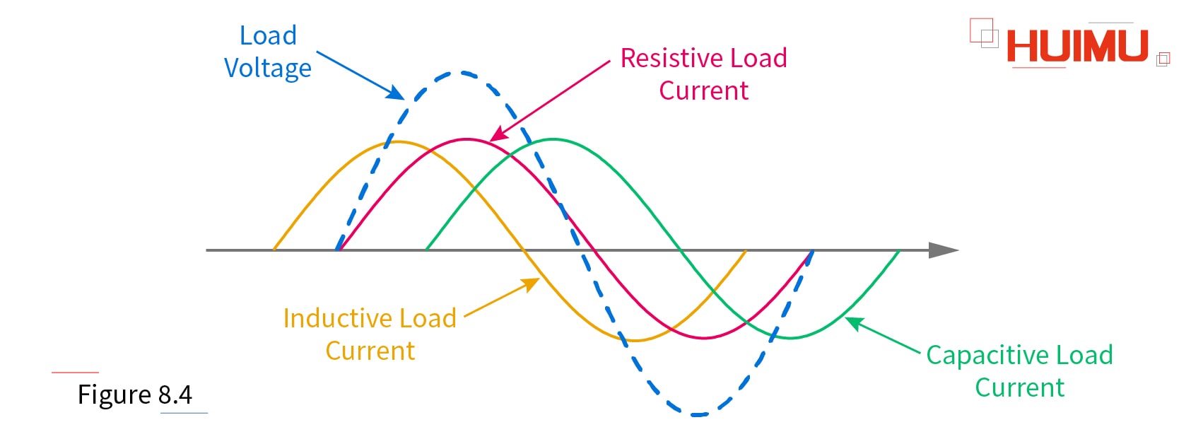
Resistive Load:
In a nutshell, a load that operates only by then resistor-type components is called the resistive load. However, some loads have low resistance at low temperatures, which results in a larger startup current. For example, when the electric furnace is just turned on, the current is 1.3-1.4 times larger than the stable current; when the incandescent lamp is turned on, the current is 10 times larger than the steady current.
Q1: What are the characteristics of the resistive load (when working)?
A1: In the DC circuit, the relationship between current and voltage is in accordance with the fundamental ohm's law, I=U/R; in an AC circuit, the current phase is the same as the phase of the voltage (compared to the power supply).
Q2: Which are resistive loads?
A2: Heating device that is heated by electric resistance (like resistance furnace, oven, electric water heater, hot oil, etc.), and lamps that rely on resistance wire to emit light (like iodine tungsten lamp, incandescent lamp, etc.).
Inductive Load:
Generally speaking, the inductive load is the load that applies the principle of electromagnetic induction (with inductance parameters), such as high-power electrical products (like refrigerators, air conditioners, etc.). The inductive load will increase the power factor of the circuit, and the current through the inductive load cannot abrupt change. At startup, the inductive load requires a much larger starting current (approximately 3-7 times) than the current required to maintain normal operation. For example, the starting current of an asynchronous motor is 5-7 times the rated value, and the starting current of the DC motor is slightly larger than the starting current of the AC motor; some metal-halide lamps have a turn-on time of up to 10 minutes, and their pulse currents up to 100 times steady state current.
Furthermore, when the power is turned on or off, the inductive load will produce a counter-electromotive force (usually 1-2 times the supply voltage), and the counter electromotive force(abbreviated counter EMF or simply CEMF) will be superimposed with the power supply voltage, and the resulting voltage is up to three times the supply voltage. So, when the load type is an inductive load, the output terminal of solid-state relay should connect a varistor with a withstand voltage of 1.6-1.9 times the load voltage. The counter EMF is an indefinite value that varies with L and di/dt, and if the current rate of change (di / dt) is too high, the SSR will be damaged. In practical applications, CEMF can be reduced by series inductance L, and the magnitude of the L inductance depends on the size and cost.
Q3: What are the characteristics of the inductive load (when working)?
A3: Inductive loads are lagging (current lags voltage). In the DC circuit, the inductive load allows current to flow through and energy to be stored in the inductor, and the current lags behind the voltage. In the AC circuit, the current phase lags behind the voltage phase (compared to the power supply), and the phase can lag a quarter cycle (or 90 degrees) at the maximum.
Q4: Which are inductive loads?
A4: Lamps that rely on energized gas to emit light (like daylight lamps, high-pressure sodium lamps or HPS lamps, mercury lamps, metal-halide lamps, etc.), and high-power electrical equipment (like motor-based equipment, compressors, relays, etc.).
Capacitive Load:
Generally, a load with a capacitance parameter is called the capacitive load, and the capacitive load will reduce the power factor of the circuit. During charging or discharging, the capacitive load is equivalent to a short circuit because the voltage across the capacitor cannot be changed abruptly.
Q5: What are the characteristics of the inductive load (when working)?
A5: Capacitive loads are leading (current leads voltage). In the DC circuits, capacitive loads prevent current from flowing, but can store energy. In the AC circuits, the current phase leads the voltage phase (compared to the power supply), and the phase can lead a quarter cycle (or 90 degrees) at the maximum.
Q6: Which are inductive loads?
A6: Device with a capacitor, such as a compensation capacitor. And power control devices such as switching power supplies, IT equipment and etc.
How to choose Solid-State Relay according to load type
1) For inductive and capacitive loads, a solid-state relay with a higher dv/dt is recommended, if there is a biggish dv/dt (voltage exponential rise rate) applied to the relay’s output terminal during the AC solid state relay turning on/off.
2) For AC resistive loads and most AC inductive loads, zero-crossing relays are available to extend the life of load and relay, and reduce their own RF interference.
3) As a phase output controller, a random type solid state relay should be used.
* Power Factor:
In electrical engineering, the power factor of an AC power system is defined as the ratio of the real power flowing to the load to the apparent power in the circuit, and is a dimensionless number in the closed interval of -1 to 1. If it is not specified the load power of the general product is the apparent power (includes both active power and reactive power). But the general specification of the inductive load often gives the magnitude of active power. For example, although a fluorescent lamp is labeled 15 to 40 watts (its active power), its ballast consumes approximately 8 watts of power, so 8W should be added to 15~40w to calculate the total power. The inductive portion of the product (i.e. the amount of reactive power) can be calculated from the given power factor.
Input Control Signal:
1) Input Control Voltage: the input control voltage has a wide range of 3~32V.
2) Input Control Current: the input current of DC SSRs and AC single-phase SSRs is generally around 10mA, and the input current of AC three-phase SSRs is generally around 30mA, which also can be customized to be less than 15mA.
3) Control Frequency: the control operating frequency of AC solid state relays generally does not exceed 10HZ, and the DC solid state relay control signal period should be greater than five times the sum of the relay's "on time" and "off time".
Mounting Method:
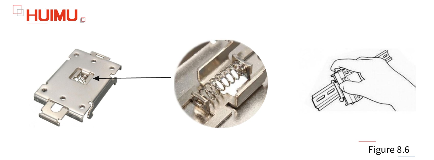
In many cases, the load power will limit whether the SSR is mounted on the PCB, the panel or the DIN rail.
Ambient Temperature:
When the relay is in the on state, it will withstand the dissipated power of P = V (on-state voltage drops) × I (load current), and the load capacity of the SSR is greatly affected by the ambient temperature and its own temperature. If the ambient temperature is too high, the load capacity of the SSR will inevitably decrease accordingly, moreover, the SSR switch may be out of control, or even be permanently damaged. Therefore, it is necessary to set a certain margin according to the actual working environment, and select the appropriate heat sink size to ensure the heat dissipation conditions. For load currents greater than 5A, a heat sink should be installed. For currents above 100A, the heat sink and fan should be equipped for strong cooling. If the SSR relay is operated at high temperatures (40 ° C ~ 80 ° C) for a long time, the load current can be reduced according to the maximum output current and ambient temperature curve provided by the manufacturer to ensure normal operation, and the load current is usually controlled within 1/2 of the rated value.
* Derating Factor:
The table below shows the recommended derating factor for the rated output current of solid-state relays applied on various loads at room temperature (the overload capability and the load surge current have been considered).
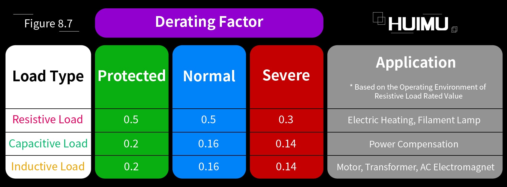
There are two ways to use the derating factor:
1) The rated current value of the solid state relay can be selected according to the derating factor of different environments and different load types. The rated current of the SSR relay is equal to the continuous current value of the load divided by the derating factor.
2) If the solid-state relay has been selected and the load type or environment changes, the load current should be adjusted based on the load curve and the derating factor in certain environment. The adjusted current multiplied by the derating factor must be lower than the rated value of the solid state relay.
In addition, when SSRs are run in applications that require more frequent operation, longer life, and more stable reliability performance, the derating factor needs to be further multiplied by 0.6 based on the data in the table. However, the load current should not be lower than the minimum output current of the solid state relay, otherwise the relay will not be switched on or the output state will be abnormal.
