§3. What is the Symbol of Solid State Relays
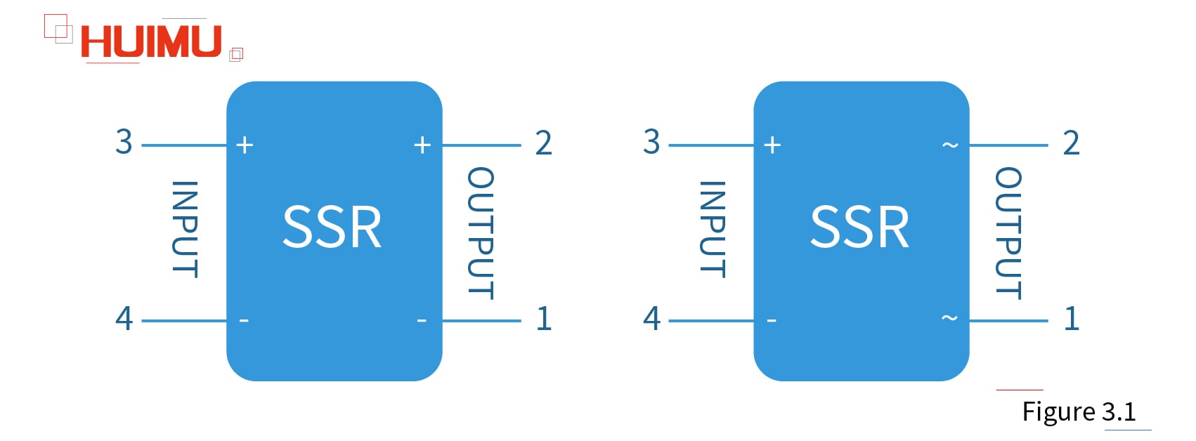
The symbol of the solid-state relay in the circuit schematic is shown below (Figure 3.1).

It should be noted that:
● The electrode symbol should be marked separately (inside or outside the frame) next to each pin of the graphic symbol.
● Input terminals and output terminals cannot usually be drawn on the same side or adjacent sides.
● When multiple solid state relays appear in the same circuit diagram, a numeric number can be added after the text symbol to distinguish the relays. (e.g. SSR1, SSR2).
