§4. What are the Types of Solid State Relays
The types of solid state relays are various and the classification standards are multifarious. The solid state relays are usually classified according to the following criteria.
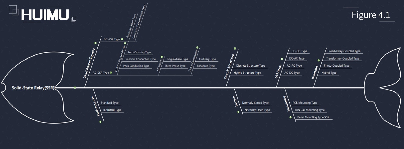
1. Load Power Supply Type:
The Solid-State Relay can be divided into DC solid state relays (DC-SSR) and AC solid-state relays (AC-SSR) according to the type of load power supply. The DC type solid state relays use the power semiconductor transistors as the switching element (such as BJT, MOSFET, IGBT) to control the ON/OFF state of the DC load power supply, and the AC type solid state relays use the thyristors (such as Triac, SCR) as the switching element to control the ON/OFF state of the AC load power supply.
1.1 DC-SSR:
Based on the input form, DC type SSR can be divided into the Resistive Input Type DC solid state relays and the Constant Current Input Type DC solid state relays.
1.2 AC-SSR:
The AC type SSR can be classified according to the following standards.
1.2.1 Control Trigger Mode:
According to the control trigger mode (the timing of turn-on and turn-off), the AC SSR can be divided into Zero-crossing Type AC solid state relays, Random Turn-on Type AC solid state relays, and Peak Turn-on Type AC solid state relays.
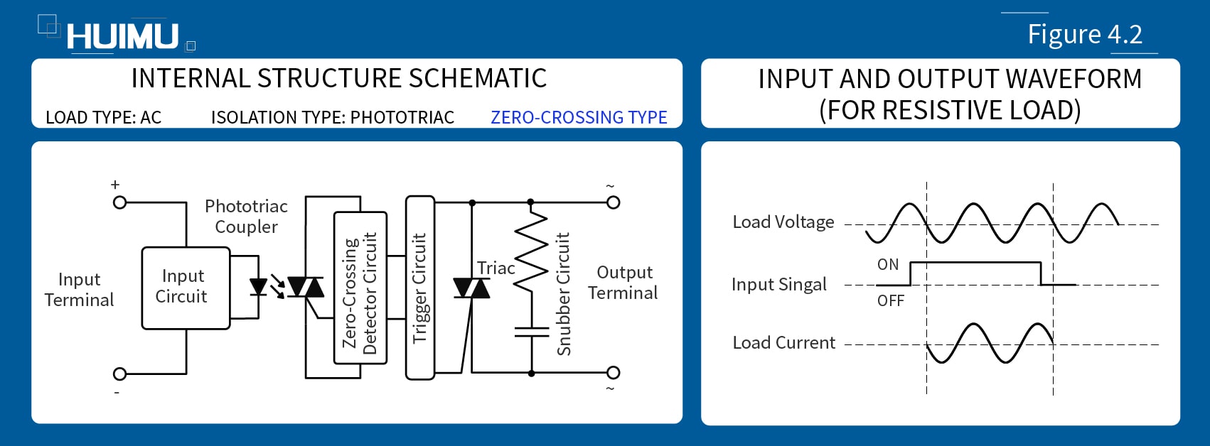
1) Zero-crossing AC solid state relays (Figure 4.2), are also known as Zero Crossing Trigger AC solid state relays, Zero cross turn-on solid state relay, Zero Switching AC solid state relays, Zero Voltage AC solid state relays, or Synchronous AC solid state relays. For the zero-crossing SSR relays, their switching state of the output circuit are synchronized with the output signal, that is, "synchronous" to the power supply. When the input signal turned on, if the load supply voltage is in the non-zero-crossing zone, the output terminal of the zero-crossing type solid state relays will not be switched on; but if the load supply voltage reaches zero zone, the output terminal of zero crossing SSR relay will be switched on, as well as, the load circuit will be turned on. This trigger mode can effectively reduce the inrush current generated during SSR turn-on, and also reduces the interference signal to the power grid and the input control circuit at the same time. In consequence, the zero-crossing solid state relays are the most common type in many fields.
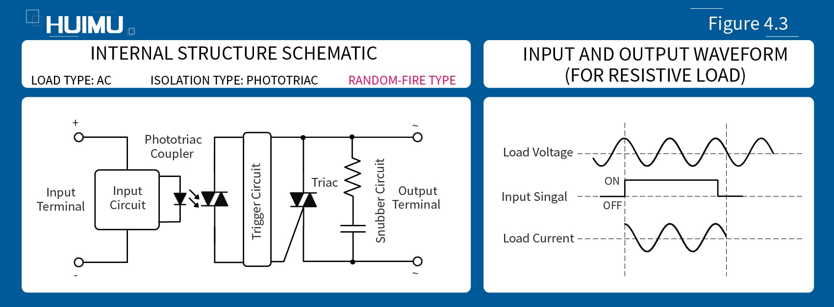
2) Random Turn-on Type AC solid state relays (Figure 4.3), are also known as Random Swtichng AC solid state relays, Random Switch On AC solid state relay, Random Conduction AC solid state relay, Random Fire AC solid state relay, Instantaneous Turn On solid state relay, Non-zero Switching AC solid state relays, Instant-on AC solid state relays, Instantaneous AC solid state relays, Asynchronous AC solid state relays or Phase Modulation AC solid state relays. The output circuit switching mode of the random type SSR relay is controlled only by the control signal and is independent of the power supply signal, i.e., "asynchronous" with the power supply. Random type solid state relays will be immediately turned on, as long as there are input signals in the input terminals, and regardless of the state of the load voltage. Since Random Solid-State Relay is turned on or off at any phase of the AC power source, a large interference signal may be generated at the turn-on instant.
3) Peak Turn-on Type AC solid state relays are also known as Peak Switching AC solid state relays, or Peak Fire AC solid state relays. When the input control signal is applied, the peak type SSR relays are turned on at the first voltage peak point of the AC output voltage to reduce the inrush current; if the input control signal is removed, the Peak Solid State Relays will be turned off.
1.2.2 Phase:
According to the phase of the AC supply, the AC-SSR can be divided into the Single-Phase AC solid state relays and the Three-Phase AC solid state relays.
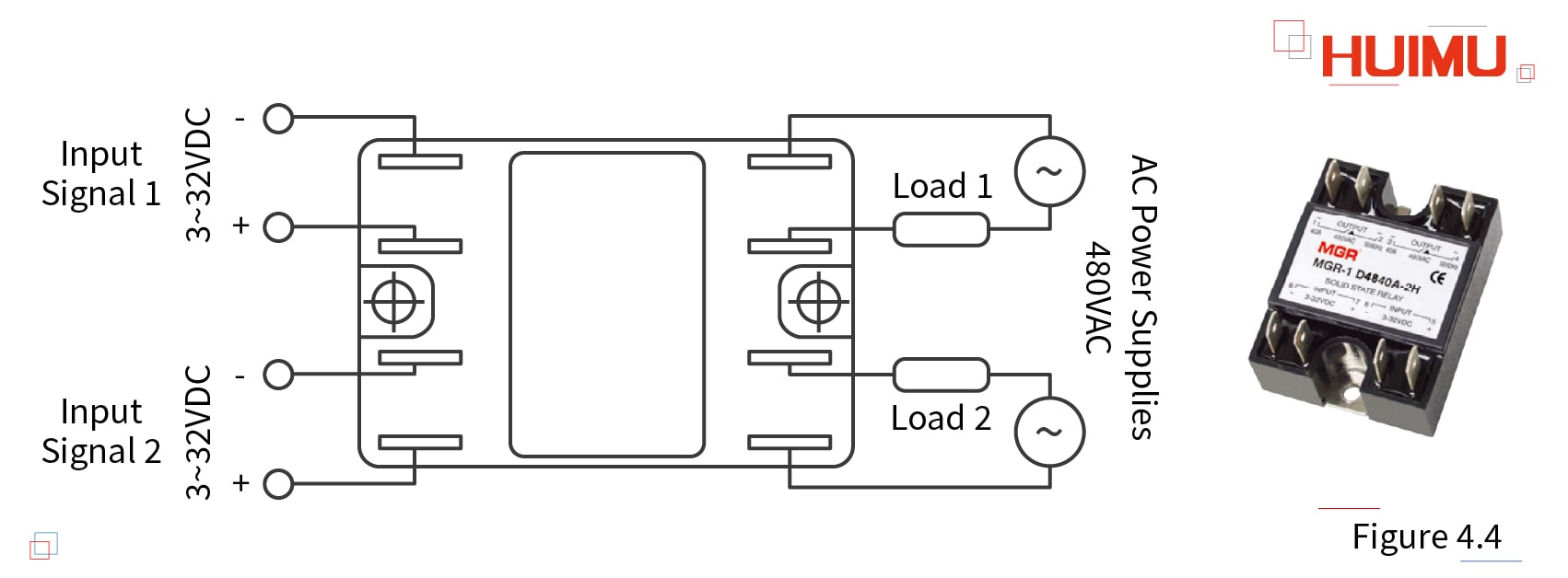
1) Based on the different function, single-phase AC solid state relays can be further divided into single-phase AC/DC solid-state relays,single-phase solid-state voltage regulators, single-phase solid-state governors,one open and one closed single-phase solid-state relays, single-phase forward and reverse solid state relays,single phase dual solid-state relays, and so on. It should be mentioned that the dual relay (Figure 4.4) which is a kind of single-phase solid-state relay that combines two single-phase industrial solid state relays into one standard industrial package with double input terminals and double output terminals, and each set of I/O terminals is independent of the other set, that is, the dual SSR relays have more contacts and can achieve more diverse control than the normal types.
2) The three-phase AC solid state relays can be directly used for the control of three-phase AC motors, and the three-phase forward-reverse AC solid-state relay (or three-phase reversible AC solid-state relay) can be used to control the three-phase forward and reverse motors (three-phase bi-directional AC motors, or three-phase bi-rotational AC motors).
1.2.3 Switch Component:
According to switch components, the AC-SSR can be divided into the Ordinary Type AC solid-state relays and the Enhanced Type solid-state relays. The ordinary type SSR relays use the Triac as output switching component, and the enhanced type SSR relays used the SCR anti-parallel as the switching component.
2. I/O form:
According to the I/O form, the solid-state relays can be divided to four types: DC input-AC output type solid state relays (DC-AC SSR relays), DC input-DC output type solid state relays (DC-DC SSR relays), AC input-AC output type solid state relays (AC-AC SSR relays), AC input-DC output type solid state relays(AC-DC SSR relays).
3. Switch Type:
According to the switch type, the SSR switches can be divided into normally open type solid state relays (or NO-SSRs) and normally closed type solid state relays (or NC-SSRs). The normally open solid-state relays will be turned on, only when the input terminals are applied with the control signal. On the contrary, the normally closed solid state relays will be turned off, when the input signal is applied to the input terminal. (Unless otherwise specified, the solid state relays in this document refer to normally open solid state relays by default.)
4. Isolation/Coupling:
According to isolation/coupling methods, the SSR can be divided into Reed Relay Coupled type solid state relays, Transformer Coupled type solid state relays, Photo Coupled type solid state relays, and Hybrid type solid state relays.
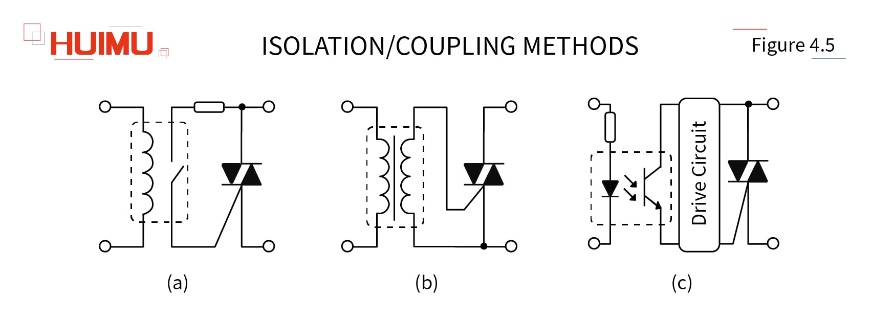
1) Reed Relay Coupling SSR (Figure 4.5, a) uses reed-switch as the isolation method. When the control signal is applied directly (or through the preamplifier) to the coil of the reed relay, the reed switch will close at once and the thyristor switch will be activated to make the load conduct.
2) Transformer Coupling SSR (Figure 4.5, b) uses a transformer as an isolation device. The transformer can convert the low power control signal from the primary coil to the secondary coil to generate a signal for driving the electronic switch. And if the input control signal is a DC voltage, a DC-AC converter is required in the input circuit. After processing by rectification, amplification or other modifications, the signal from the secondary coil can be used to drive the switching component.
3) Photo Coupling SSR (Figure 4.5, c), also known as photo-isolated SSR, or opto-coupled SSR, uses an optical coupler as an isolator. The optical coupler is an opto-isolator that consists of an infrared source (usually, a light-emitting diode, or LED) and a photo-sensitive semiconductor component (such as a photosensitive diode, a photo-sensitive transistor, and a photo-sensitive thyristor). According to the different components (Figure 4.6), the opto-coupler can be into Opto-Diode Coupler(Photo-Diode Coupler), Opto-Transistor Coupler (Photo-Transistor Coupler), Opto-SCR Coupler (Photo-SCR Coupler), and Opto-Triac Coupler (Photo-Triac Coupler).
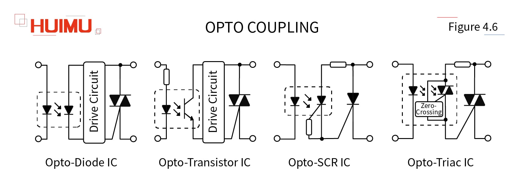
The photo-semiconductor device detects the infra-red radiation from the LED, and then produces a signal to drive the semiconductor switch. Compared with reed relay and transformer, the optical isolator has better physical isolation ability, to ensure the electrical insulation between high voltage output load circuit and low voltage input signal circuit. And on account of the excellent isolation performance and very compact size of the optocoupler, the optocoupler solid state relay is used in a very wide range of applications.
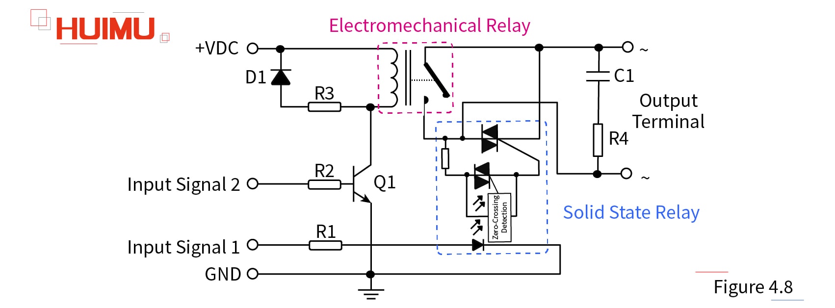
4) Hybrid solid state relay is a special solid state relay which combines the advantages of EMR and SSR, with high efficiency and low power consumption. The input and output circuits of the hybrid solid-state relays are composed of an SSR relay and a reed switcher (or a micro-electromagnetic relay) in parallel, controlled by different control signals (Figure 4.7).
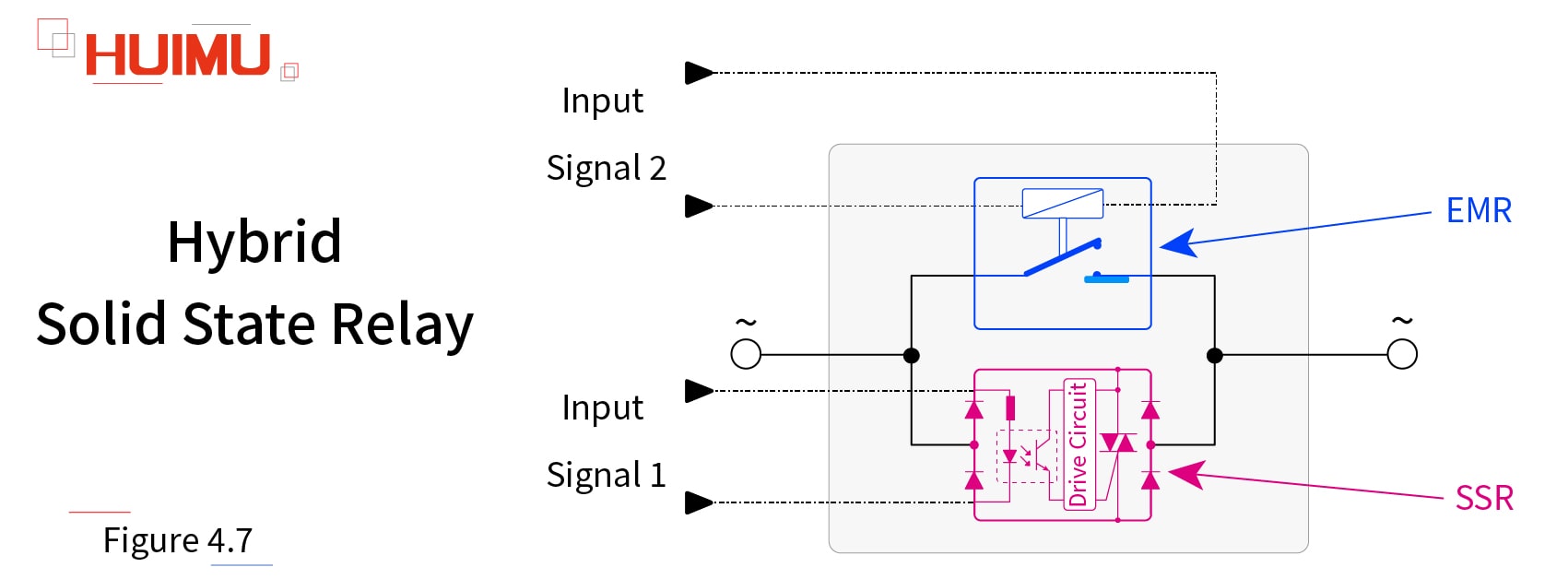
When Input Signal 1 is applied, the SSR immediately switches to the on state. Since the electronic switch has no moving parts, it can switch the load stably and quickly, and does not generate an arc due to high line voltage or heavy surge current during switching. After the load current is generated, the EMR will be controlled by the control signal 2 and switched on. Because the EMR is connected in parallel with the SSR, the output contact of the EMR is energized without voltage, and there is no arcing across the contacts. Then after a certain delay, the contact bouncing of the EMR settles down, and the SSR will be turned off. The EMR works almost with no heat, so the hybrid SSR relays can be run without a heat sink installed.
5. Circuit Structure:
According to different circuit structure, the solid-state relay can be divided into Discrete Structure Type solid state relays and Hybrid Structure Type solid state relays. The discrete structure solid state relays are mostly assembled by discrete components and printed-circuit board, and then packaged by epoxy resin potting, plastic sealing or resin wrapping. The hybrid structure solid state relays use thick-film combine technology to assemble discrete components and semiconductor integrated circuits (IC), and then encapsulate them in a metal or a ceramic housing.
6. Performance:
According to the performance, the solid-state relay can be divided into the Standard Type solid state relays, and the Industrial Type solid state relays. The rated current of the standard solid-state relay is generally 10A to 120A, and the rated current of the industrial solid-state relay is relatively large, can be 60A to 2000A or larger. Therefore, the industrial SSR relay can meet the strict requirements of the industrial environment and industrial machinery.
7. Mounting:
According to the mounting methods, the solid-state relays can be divided into Panel Mounting Type solid state relays (or Surface Mounting Type), DIN Rail Mounting Type solid state relays, and Printed Circuit Board Mounting Type solid state relays (or PCB Mounting Type). And the PCB mounting SSR can be further divided into Socket Mounting Type SSR (or Plug-in Mounting Type) and Bracket Mounting Type SSR (or Flange Mounting Type). The plug-in solid-state relays with many package standard (like SIP, Mini-SIP, and DIP), can be directly soldered on the printed circuit board, relying on natural cooling, without the need for a heat sink; the flange mounting solid state relays require the additional metal plate or heat sink to dissipate heat.
8. Application:
According to the application, the solid state relays can be divided into General Application Solid State Relays, Two-way Transmission Solid State Relays, Automotive Solid-State Relays, Latching Solid State Relays (the input signal runs as a logical Exclusive OR, or XOR, so any input can latch/unlatch the output), and so on.
The latching relay can keep conducting and continuously output the control signal even if cutting off the control current, and it can only be turned off by inputting the reverse current or the off button. The latching is usually used in high-voltage circuits to avoid the expansion of accidents.
