BRIEF SAFETY MANUAL

BRIEF SAFETY MANUAL

SAFETY FIRST!

There is nothing more important than protecting your own safety.

Please strictly observe the safe operation rules and operation instruction. If you can't keep yourself safe, stop operating and leave immediately. If you encounter an uncertain or unsolvable problem, please consult the relevant technical personnel in time, please do not take risks. Before using, testing, maintaining electrical devices, you need to know the following:

§1.What are the dangers of electricity?

Know the dangers of electricity. More details via sales@huimultd.com
Electricity makes our life more convenient, but at the same time it can also causes great damage to our vulnerable body because of its enormous energy. The electric damage to the human body can be divided into: Electric Shock (such as tingling, burning sensation, spasm, paralysis, coma, ventricular fibrillation or stoppage, difficulty breathing or breathing stop); Electric Injury (such as electric burn, skin metallization). When the electric current passes through the heart, it can cause heart dysfunction, destroying the original contraction and expansion rhythm, heart failure, and ending blood circulation, causing death due to hypoxia in the brain. When the electric current passes through the central nervous system (brain and spinal cord), it can cause breathing stop and paralysis. The thermal effect of the electric current can cause electrical burns. The chemical effect of the electric current can cause electrical burns and metallization of the skin. The electromagnetic effect of the electric current will also produce radiation. The above injury may can cause secondary damage.
The level of current. More details via sales@huimultd.com
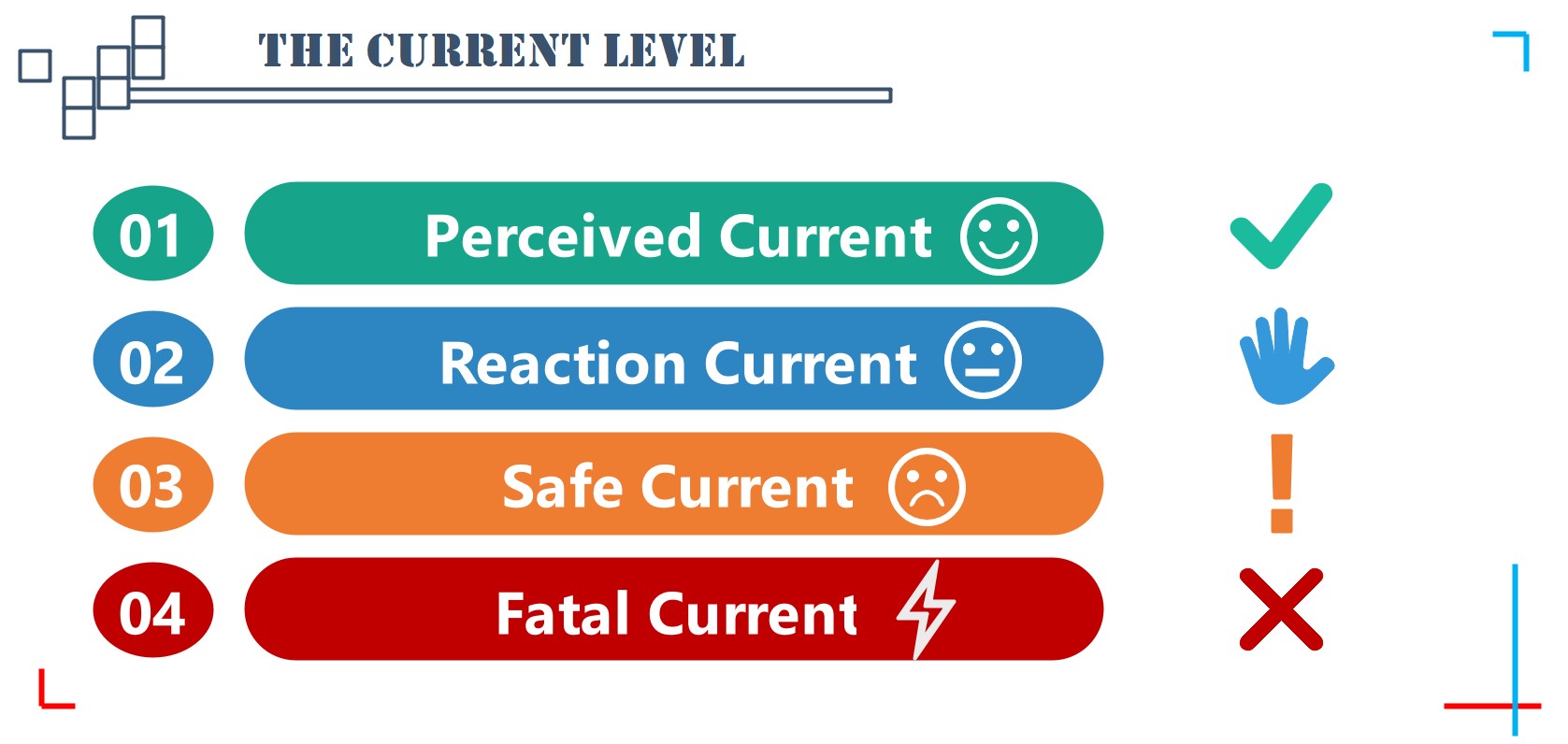
According to the different reactions of the human body after contacting the current, the current can be divided into the following four levels:
1. Perceived Current: The minimum current value that can be felt by the human body but does not cause harmful physiological reactions, which is 1mA (AC, 50~60Hz) or 5mA (DC) for adults.
2. Reaction Current: The minimum current value that can cause muscles to contract unconsciously, which is 5mA (AC, 50~60Hz) or 25mA (DC) for adult.
3. Safe Current: The maximum current value that the human body can freely get rid of the power supply without pathological damage after an electric shock, which is 10 mA (AC, 50~60Hz) or 50mA (DC) for adults.
4. Fatal Current: The minimum current value that can cause ventricular fibrillation and is life-threatening, which is typically 50 mA (AC, 50~60Hz), 80mA (DC) for adults.

The electrical resistance of the human skin is 1000~3000Ω (normally), and 800~1000Ω (when the skin horny outer layer is destroyed), so safety voltage can be calculated according to Ohm's law (I=U/R). Since the skin resistance is affected by many factors (such as clothing, sweat, conductive dust in the air), choosing the safe voltage is more reasonable instead of the safe current. In a dry environment, the safety voltage is 24VAC (50~60Hz) or 120VDC; in a humid environment, the safety voltage is 12VAC (50~60Hz) or 40VDC.

§2. How to avoid the danger of electricity?

Safety measures to protect human safety. More details via sales@huimultd.com

1. Electrical Insulation

The electrically charged object (or charged body) must be enclosed by a non-conductive insulating material. Keeping the insulation of distribution lines and electrical equipment is the most basic prerequisite to ensure personal safety and normal operation of electrical equipment. The performance of electrical insulation can be measured by its insulation resistance and dielectric strength.

2. Safety Distance

The electrically charged objects should be kept at a certain distance from the ground, the human body, other charged objects, and other facilities or equipment. Outside such safety distance, there is no danger when the human body or object is close to the charged body, such as the safety distance for the power distribution device, the maintenance safety distance, and the operation safety distance.

3. Safe Current Carrying Capacity

The safe current carrying capacity is the maximum amount of current that is allowed to continuously pass through the device. If the current exceeds the safe current carrying capacity of the device, the heat generated by the device will exceed its allowable value, which will cause damage to the insulation layer and even cause electric leakage and fire. Therefore, before selecting a device, you need to know its safe current carrying capacity.

4. Marking

The clear, accurate and uniform marking is another important prerequisite for ensuring the safety of electricity. For instance, the hazardous zone should be marked with a warning marking, the device with different structure and different parameters can be identified with the model number marking, the wires with different nature and different purposes can be identified by color marking (For example, Phase A wire is yellow, Phase B wire is green, Phase C wire is red, exposed grounding wire is black; AC loop of secondary system circuit is yellow, the negative power supply is blue, and the signal and warning circuits are white).

§3. How to operate safely

Safety precautions to operate safely. More details via sales@huimultd.com

1. Protective Equipment

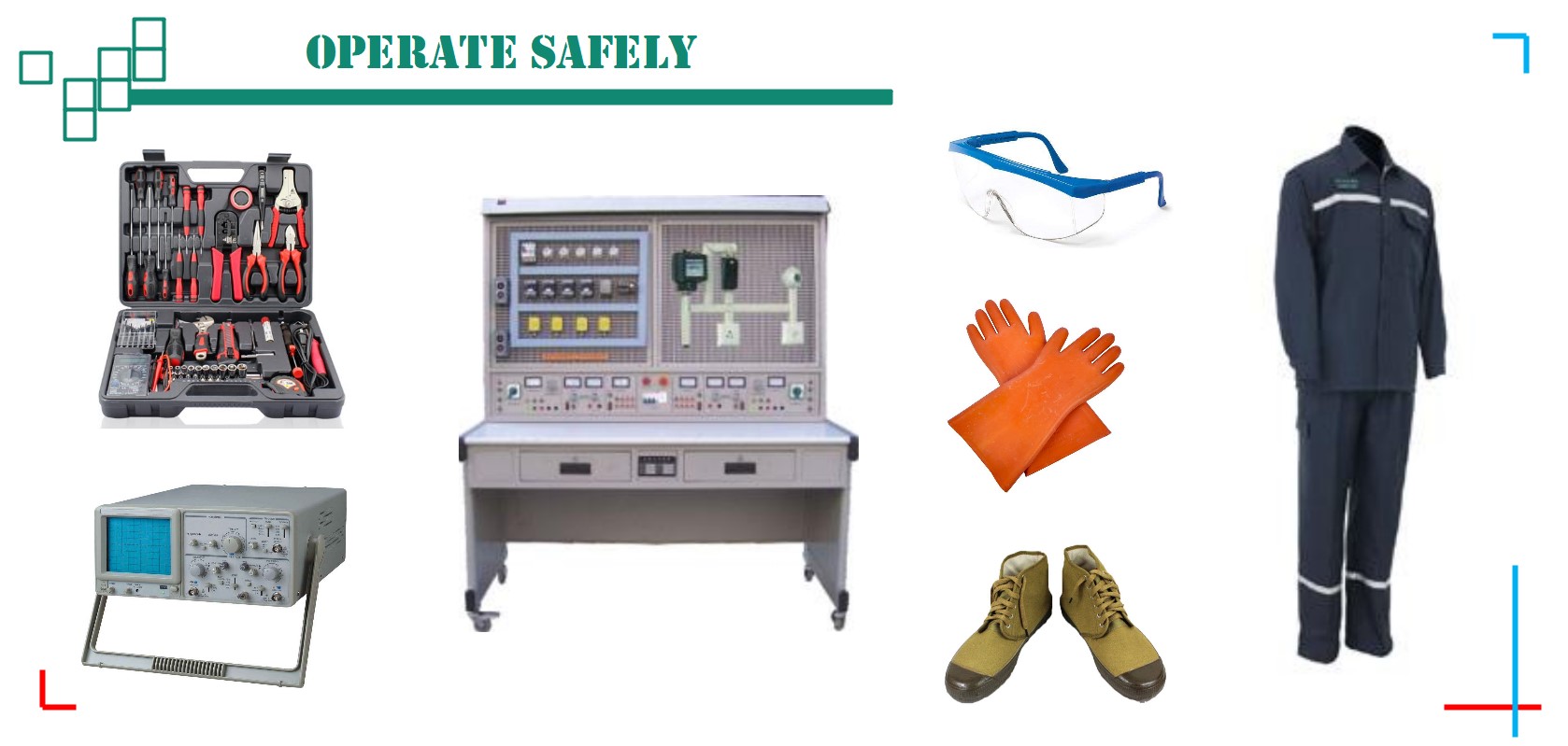
Before operating electrical device, please ensure that you have worn rubber-insulated gloves, insulated shoes, anti-static clothing, safety goggle and other protective equipment. And you also need to confirm that there are fire-fighting facilities or other safety facilities within the specified range.

2. Operating Tools

You need to check if the tool you are using has insulation ability, if the insulation material is aged and dropped, it should be replaced immediately. If there is a risk of explosion and fire, use an explosion-proof tool.

3. Operation Precautions

● Please do not operate with power.
● Please ensure that the working environment is dry, the temperature is suitable, and the ventilation conditions are good.
● Please make sure the working table is clean, and free of dust, metal debris, etc.
● Please make sure that wires are correctly connected according to the marking. For DC devices, please do not reverse the positive and negative poles.
● Please ensure that all electrical and electronic equipment is working within its rated value.
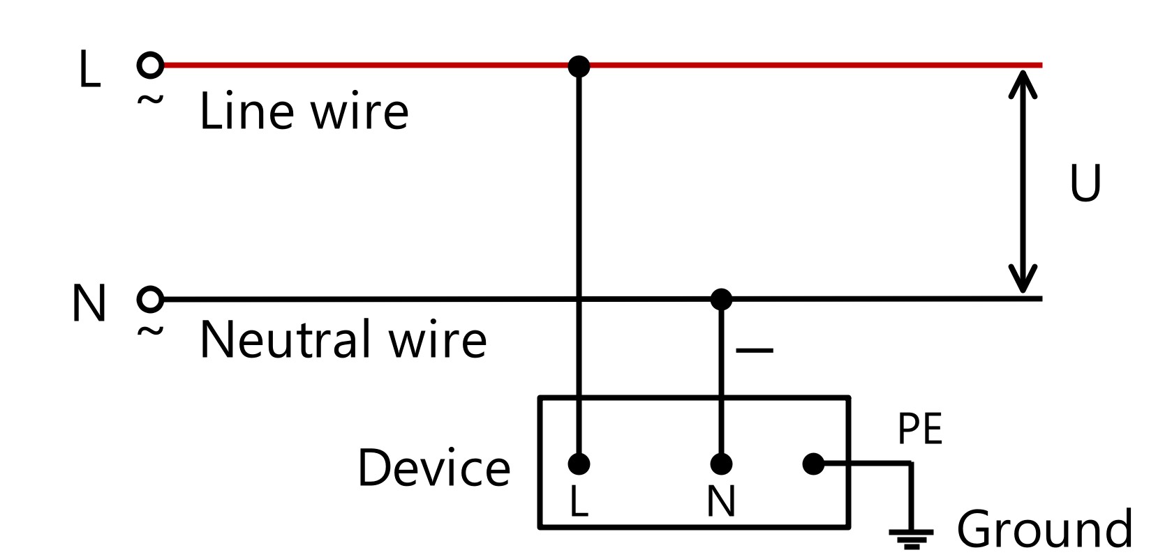
● Please make sure all the device is safely grounded.
● If there is a large capacitance or a large inductance in the device, you cannot directly touch it even after the power is turned off, because it will output a high voltage of several thousand volts in an instant. You should wait for its natural discharge or force discharge it using auxiliary equipment under safe conditions.
● Before using the voltage regulating device, make sure the regulator is in the initial state (zero voltage, 0V).
● When using electrical or electronic equipment, once you smell the burnt smell, hear abnormal sounds, see abnormal conditions such as flashing of the display or indicator light, please immediately turn off the power and check the equipment.
● If the device needs to be replaced due to a malfunction, it is recommended to use a device with the same model or technical parameters.
● Please do not press the stop button immediately after starting the electrical motor, because its starting current is 6-7 times the rated current, if it stops immediately, it will burn out other equipment.


The above content was updated on Nov. 16, 2019.

Electrical Calculation

Electrical Calculation

We make a list of some common calculation formulas that you might use when choosing a solid state relay (SSR)/solid state module (SSM) or designing a circuit.
Attention: HUIMU Industrial (HUIMULTD) assumes no liability for errors in data nor in safe and/or satisfactory operation of equipment designed from this information.

Electric Power Calculation Formulas


Single Phase Load. More details via sales@huimultd.com

● Single Phase Load

P=U·I·cosφ
U is the Voltage (usually 220VAC), I is the Current.
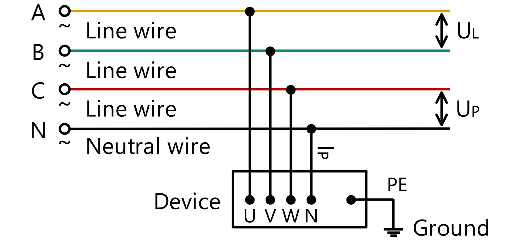
Three Phase Load. More details via sales@huimultd.com

● Three Phase Load

P=√3·UL·IL·cosφ=3·UP·IP·cosφ
UL is the Line Voltage (normally 380VAC), IL is the Line Current, UP is the Phase Voltage (normally 220VAC), IP is the Phase Current.

● Power Factor (cos φ)

If the load type is resistive load (such as electric heater), then cos φ=1; If the load type is inductive load (such as an electric motor), then 0<cos φ<1. Take electric motor as a example, when the electric motor is fully loaded, the active current is the largest, the reactive current is the smallest, and the power factor is about 0.85; when the load is light or no load, the active current is small, the reactive current is large, and the power factor is between 0.4 and 0.7. Thus, we usually take a power factor of 0.78 or 0.8. If the load type is capacitive load (such as power compensator), then cos φ<0.

● Peak Value, Effective Value, Average Value

The AC voltage is a sine wave, and its voltage value changes periodically from 0 to the maximum value (UMAX), so its peak value (UPK) is equal to the maximum value. The AC effective value is specified by the thermal effect of the current, that is, let an AC current and a DC current pass through resistors with the same resistance value respectively, and if they generate equal heat in the same time, then the effective value of this AC current is equaled to the value of this DC current. Since the effective value of the sinusoidal AC voltage is equal to its root mean square value (URMS or U), URMS is generally used to represent the effective value of the AC voltage. Normally, the AC voltage value we detect through detection equipment (such as multimeters) is the effective voltage value, and the AC voltage value marked on the electrical equipment is also the effective value (such as 220VAC, 380VAC). The average AC voltage (UAV) is the average voltage value over a period. The average AC voltage is equal to the integral of the voltage in one cycle divided by 2π (the time in one cycle). Theoretically, the DC voltage value obtained after full-wave rectification of the AC voltage is equal to the average value of the AC voltage.
UPK=√2·URMS=1.414·URMS
UAV=2/π·UPK=0.637·UPK
Similarly, according to Ohm's law, we can get the peak value (IPK or IMAX), the effective value (IRMS), and the average value (IAV) of the AC current.
IPK=√2·IRMS=1.414·IRMS
IAV=2/π·IPK=0.637·IPK
Because the value of DC current or DC voltage is constant, they have no maximum value, effective value, and average value.

Derating Factor Calculation Formulas


Since the performance of the solid state relay/solid state module is affected by the working environment and the load type, the Derating Factor (or Current Multiple Factor) should be considered when selecting the rated current value of the solid state relay/solid state module.
Derating Factor. More details via sales@huimultd.com
IR=IL
IR is the rated current value of the solid state relay/solid state module;
IL is the DC load current value or the AC load current effective value (rms value);
α is the derating factor.
According to the working environment of the solid state relay/solid state module (ventilation, temperature, service time, etc.), the derating factor can be divided into three levels: Protected, Normal and Severe.
For resistive loads (such as electric heater, incandesc ent lamp, etc.), α = 0.5 (Protected), α = 0.5 (Normal), α = 0.3 (Severe);
For inductive loads (such as motor, transformer, etc.), α = 0.2 (Protected), α = 0.16 (Normal), α = 0.14 (Severe);
For capacitive loads (such as power compensator, etc.), α = 0.2 (Protected), α = 0.16 (Normal), α = 0.14 (Severe).
Current Multiple Factor. More details via sales@huimultd.com
Current Multiple Factor is the inverse of Derating Factor.
IR=IL·β
IR is the rated current value of the solid state relay/solid state module;
IL is the DC load current value or the AC load current effective value (rms value);
β is the current multiple factor.
For resistive loads (such as electric heater, incandescent lamp, etc.), β = 2 (Protected), β = 2 (Normal), β = 3 (Severe);
For inductive loads (such as motor, transformer, etc.), β = 5 (Protected), β = 6 (Normal), β = 7 (Severe);
For capacitive loads (such as power compensator, etc.), β = 5 (Protected), β = 6 (Normal), β = 7 (Severe).
For example, if you need a DC to AC Panel solid state relay to switch a 220VAC, 10A resistive load, and require this solid state relay to work uninterrupted in a poor ventilation environment, then according the derating factor β = 3 (Severe), you should choose MGR-1D4830 (DC to AC, load: 480VAC, 30A).

Varistor Calculation Formulas


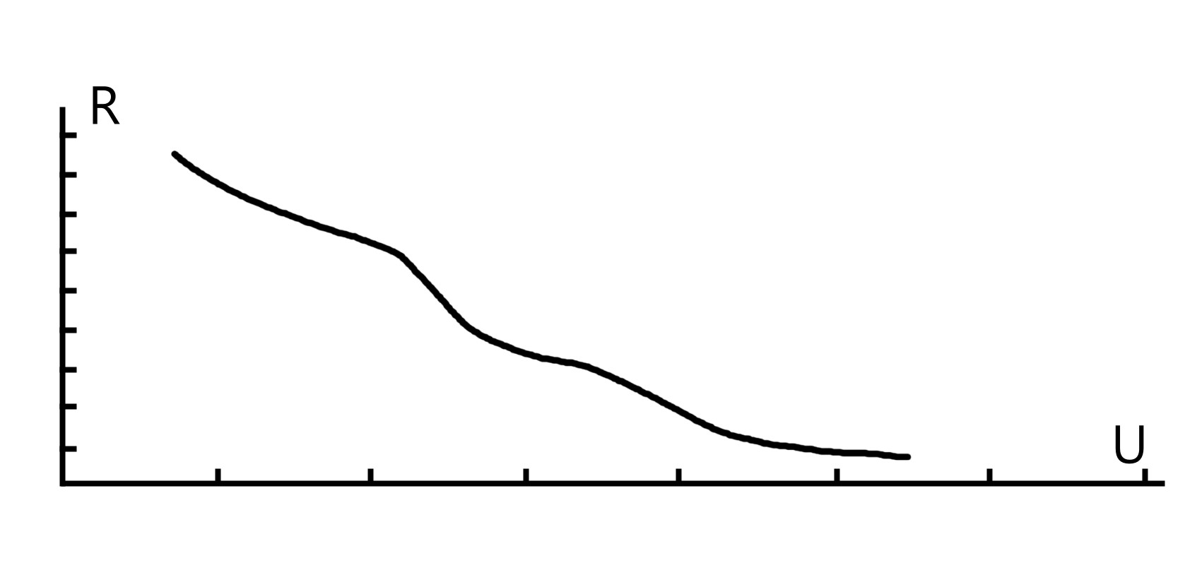
If the load peak voltage is high, be sure to connect the varistor (such MOV, ZNR) in parallel to the output terminal of the solid state relay/ solid state module.
U-R waveform of Varistor. More details via sales@huimultd.com
VimA=V1mA=(a·v)/(b·c)
VimA is the varistor voltage when the current is XmA. Due to the current value is usually set at 1mA, it can also be expressed as V1mA; a is the voltage fluctuation coefficient, generally 1.2; b is the varistor error value, generally 0.85; c is the aging coefficient of the component, generally 0.9; v is the DC operating voltage, or the AC rms voltage.
Therefore, the above formula can be simplified as:
For DC circuit,VimA≈1.6·v
For AC circuit,VimA≈1.6·Vp=1.6·√2·VAC
Vp is the peak voltage, VAC is the effective value.
Generally, the varistor voltage is 1.6 times the load voltage, but when the load is an inductive load, the varistor voltage should be 1.6-1.9 times the load voltage to ensure safety.

Rectifier Circuit Calculation Formulas


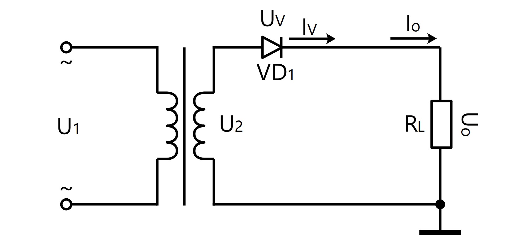
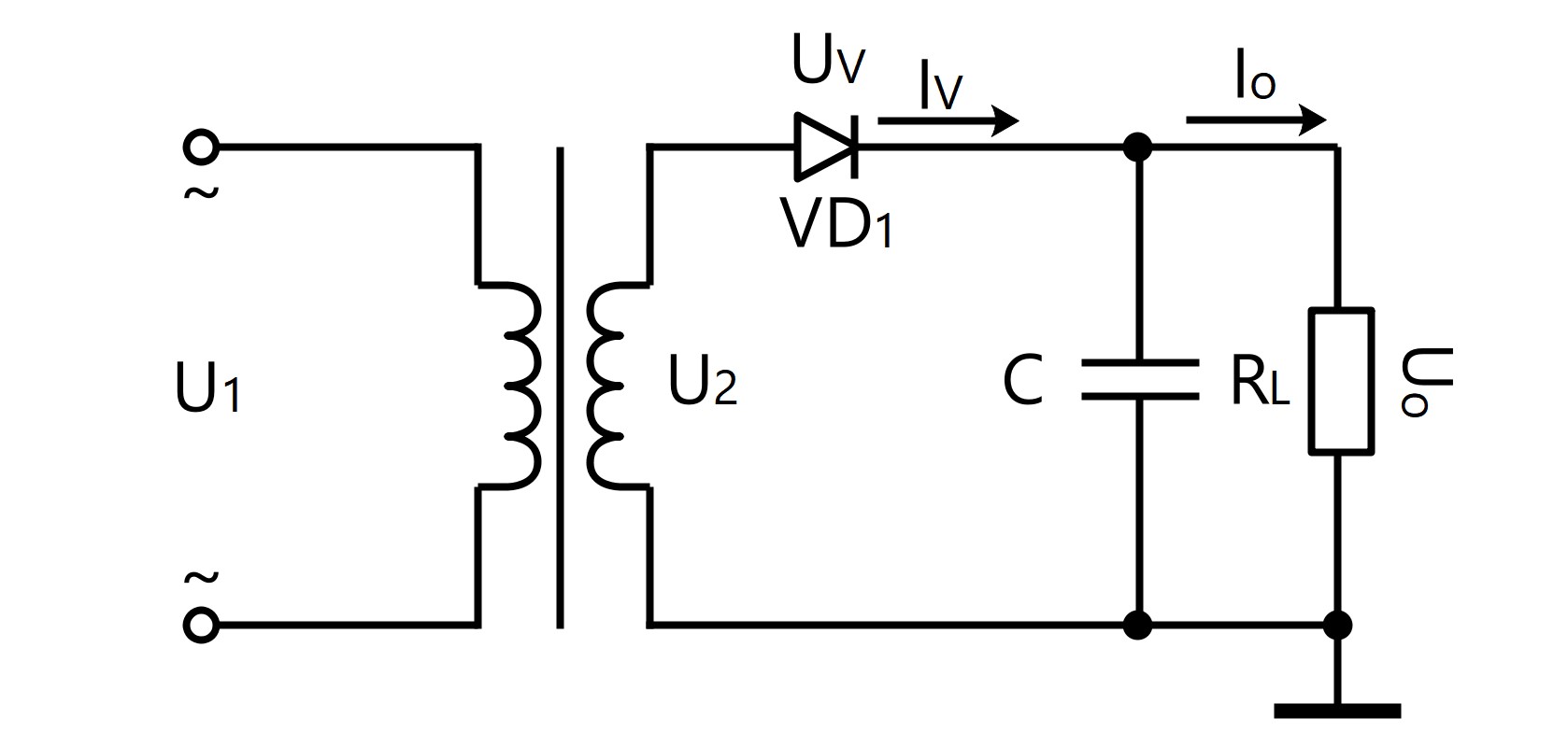
Single-Phase Half-Wave Rectification Filter Circuit. More details via sales@huimultd.com

● Single-Phase Half-Wave Rectification Circuit

U0=0.45·U2
I0=0.45·U2/RL
IV=I0
URM=√2·U2
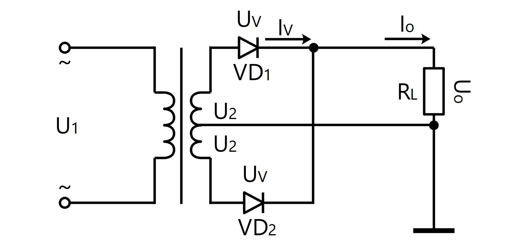
Single-Phase Half-Wave Rectification Circuit. More details via sales@huimultd.com

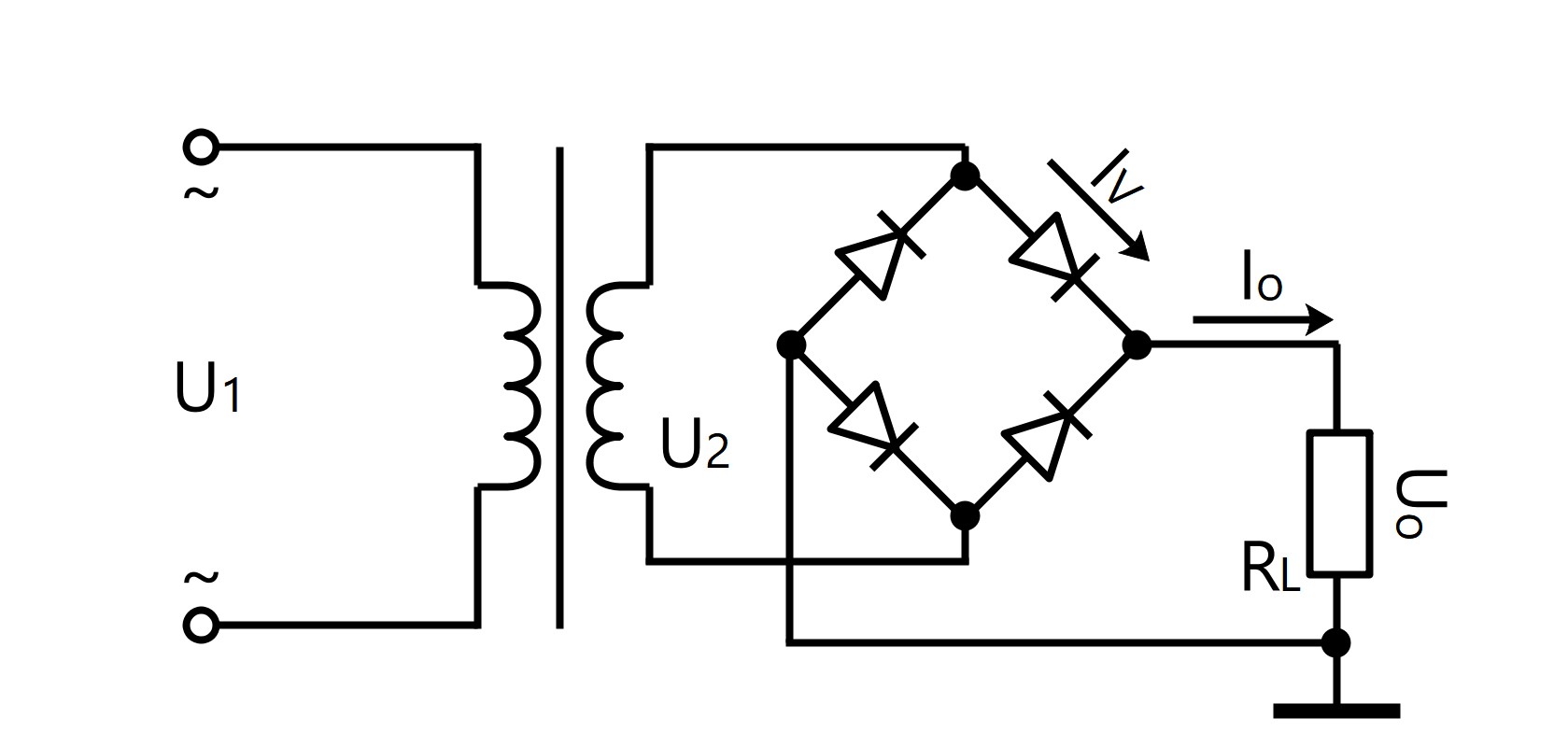
● Single-Phase Full-Wave Rectification Circuit

U0=0.9·U2
I0=0.9·U2/RL
IV=1/2·I0
URM=2·√2·U2
Single-Phase Full-Wave Rectification Circuit. More details via sales@huimultd.com

● Single-Phase Bridge Rectification Circuit

U0=0.9·U2
I0=0.9·U2/RL
IV=1/2·I0
URM=√2·U2
Single-Phase Bridge Rectification Circuit. More details via sales@huimultd.com

● Single-Phase Half-Wave Rectification Filter Circuit

U0=U2
I0=U2/RL
Iv=1/2·I0
URM=2·√2·U2
C≥(3~5)·T/RL
T=1/f, if f=50Hz, then T=1/50=20ms
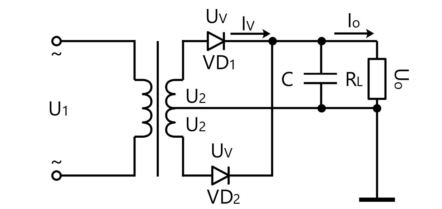
Single-Phase Full-Wave Rectification Filter Circuit. More details via sales@huimultd.com

● Single-Phase Full-Wave Rectification Filter Circuit

U0=1.2·U2
I0=1.2·U2/RL
Iv=1/2·I0
URM=√2·U2
C≥(3~5)·T/2RL
T=1/f, if f=50Hz, then T=1/50=20ms
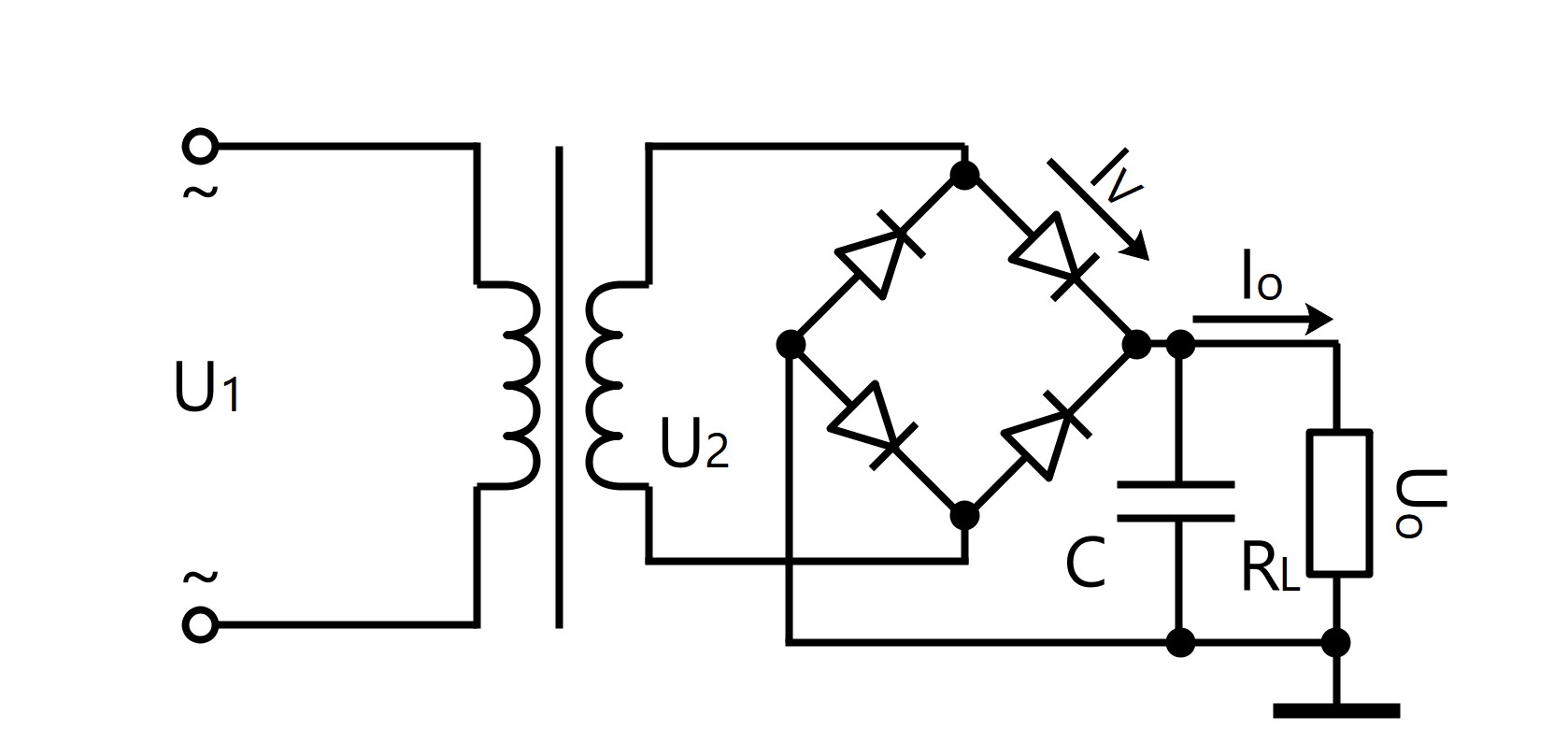
Single-Phase Bridge Rectification Filter Circuit. More details via sales@huimultd.com

● Single-Phase Bridge Rectification Filter Circuit

U0=1.2·U2
I0=1.2·U2/RL
Iv=1/2·I0
URM=√2·U2
C≥(3~5)·T/2RL
T=1/f, if f=50Hz, then T=1/50=20ms
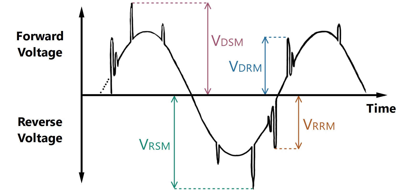
What are VDSM, VDRM, VRSM, and VRRM? More details via sales@huimultd.com
VRSM=VRRM+200V
VRSM (Non-Repetitive Peak Reverse Voltage), is the maximum allowable surge value of reverse voltage that can be applied to the reverse direction of the device; VRRM (Repetitive Peak Reverse Voltage), is the maximum allowable value of reverse voltage that can be repeatedly applied to the reverse direction of the device.
VDSM =VDRM +200V
VDSM (Non-Repetitive Peak Off-State Voltage), is the maximum allowable surge value of off-state voltage that can be applied to the forward direction of the device; VDRM (Repetitive Peak Off-State Voltage), is the maximum allowable value of off-state voltage that can be repeatedly applied to the forward direction of the device.
It2=ITSM2·tw/2
tw is the half sine period; ITSM it the maximum non-repetitive on-state surge current in one cycle; if the frequency is 50Hz, It2=0.005 ITSM2 (Amps2·sec)

Heat Generation Calculation Formulas


When the solid state relays are working, the output circuit has a voltage drop of 1~2V. When the solid state modules (or power modules) are working, the output circuit has a voltage drop of 2~4V. And the electrical energy they consume is transmitted as heat, and this heat is only related to their operating current. The solid state relay has a calorific value of 1.5 watts per ampere (1.5 W/A) and the solid state module has a calorific value of 3.0 watts per ampere (3.0 W/A). The heat generated by the three-phase circuit is the sum of the heat generated by each phase.
Single Phase or DC solid state relay: P=1.5·I
Single Phase or DC solid state module: P=3.0·I
P is the heat generated by solid state relay/solid state module, and the unit is W; I is the actual load current, and the unit is A.
Normally, if the load current is 10A, a heat sink must be equipped. If the load current is 40A or higher, an air-cooled or water-cooled heat sink must be equipped.

Heat Dissipation Calculation Formulas


The heat dissipation performance of the heat sink is related to its material, shape, temperature difference, and etc.
Q=h·A·η·ΔT
Q is the heat dissipated by the heat sink; h is the total thermal conductivity of the heat sink (W/cm2·°C), generally aluminum material is about 2.12W/cm2·°C, the copper material is about 3.85W/cm2·°C, and the steel material is about 0.46W/cm2 °C; A is the surface area of the heat sink (cm2); η is the heat sink efficiency, which is mainly determined by the shape of the heat sink; ΔT is the difference between the maximum temperature of the heat sink and the ambient temperature (°C).
Therefore, it can be obtained from the above formula that the larger the surface area of the heat sink is, the larger the difference from the ambient temperature is, and the better the heat dissipation performance is.

Common Unit Conversion


1MΩ=103kΩ=106Ω=109
1F=103mF=106μF=109nF=1012pF
1H=103mH=106μH
1MV=103kV=106V=109mV=1012μH
1kA=103A=106mA=109μA
1W=103mW=1J/s=1V·A
1HP=0.75kW
1kW·h=103W·h=103V·A·h=10V·mA·h=3.6·106J
1cm=10mm=0.39in
1cm2=0.16sq in
°F=1.8°C+32
K=°C+273.15


The above content was updated on Nov. 29, 2019.
There may be errors and omissions during the content collation and upload process, so all things above are for reference only. If you find any problems, your correction will be grateful.

What are solid state modules?

§1. What is a Power Module

In this chapter you will learn what are solid state modules.

The power module (PM) is also called electronic power module, or solid state power module, which is a module that encapsulates power electronic components combination into a solid state structure according to a certain functional. Through the internal integrated circuit (IC), the power module can output the power and adjust the power of the load. According to the main functions, we divide solid-state modules into solid state voltage regulation modules and solid state rectification modules.

1.1 Solid State Voltage Regulation Module
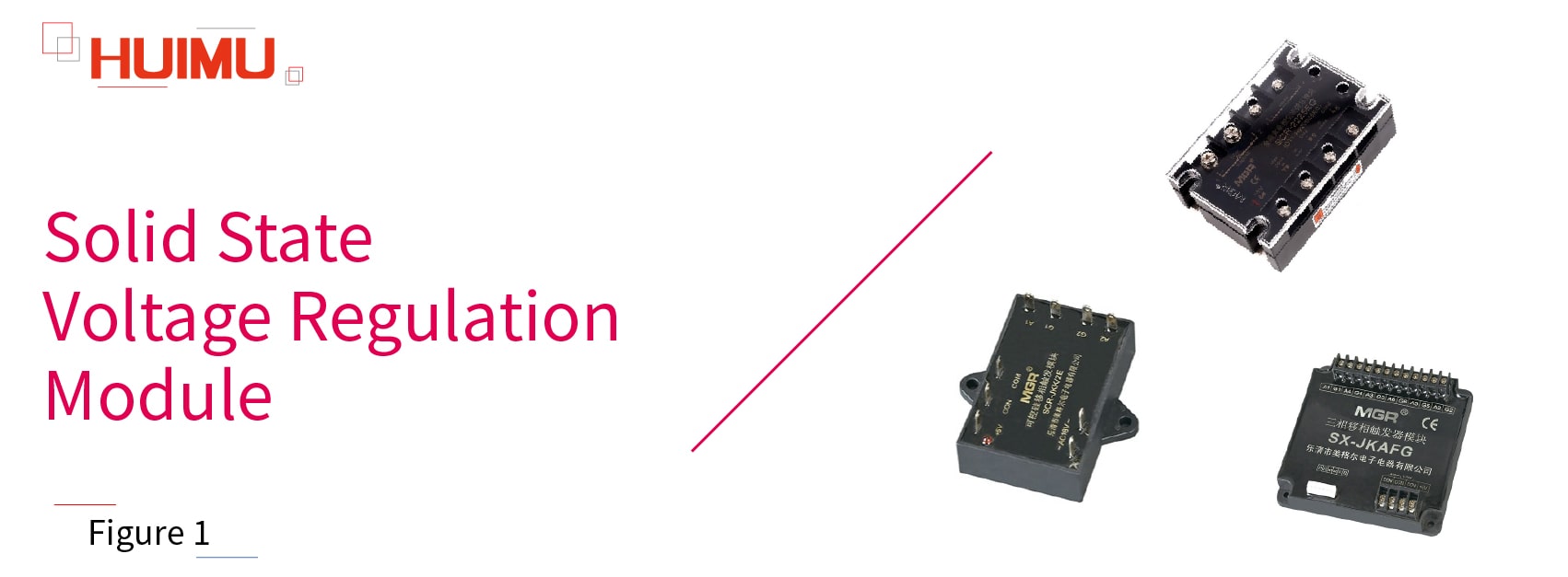
Copyright @ huimultd.com The solid state voltage regulation module (also known as the solid state power voltage regulation module, the solid state power regulating module, the solid state voltage regulating module and the solid state power voltage regulator module) are used to adjust the voltage or power of the AC load. Generally, the solid state voltage regulating module is integrates the synchronous transformer, the power output circuit, the phase shift circuit, the detection circuit, and can be directly connected to the load to control it. Solid state voltage regulator modules are widely used into various fields, such as scientific research, experiment, detection, heating insulation, soft start.

The solid state phase-shift module (or solid state phase-shifting module) is a type of voltage-regulating module, but it can only output a phase-shifting signal and cannot be directly connected to the load. Generally, it requires a set of solid-state relays (or power thyristor circuits) and a synchronous transformer to achieve the voltage regulation function.

According to the phase, the solid-state voltage regulating module can be divided into: single-phase solid-state voltage regulator modules, three-phase solid-state voltage regulator modules.

According to whether the loop is closed, the solid-state voltage regulating module can be divided into closed-loop type and open-loop type (unclosed-loop type)

According to whether the strong current parts and weak current parts are isolated, the solid-state voltage regulating module can be divided into full isolation type and non-full isolation type.

According to the number of controlled loads (channels), the solid-state phase-shift module can be divided into: single channel solid-state phase-shift module (or single phase solid-state phase-shift module), dual channel solid-state phase-shift module, three channel solid-state phase-shift module (or three phase solid-state phase-shift module).

According to the external power output device, the solid-state phase-shift module can be divided into: external solid state relay type phase-shift modules, and external thyristor power circuit type phase-shift modules.

1.2 Solid State Rectification Module
Copyright @ huimultd.com

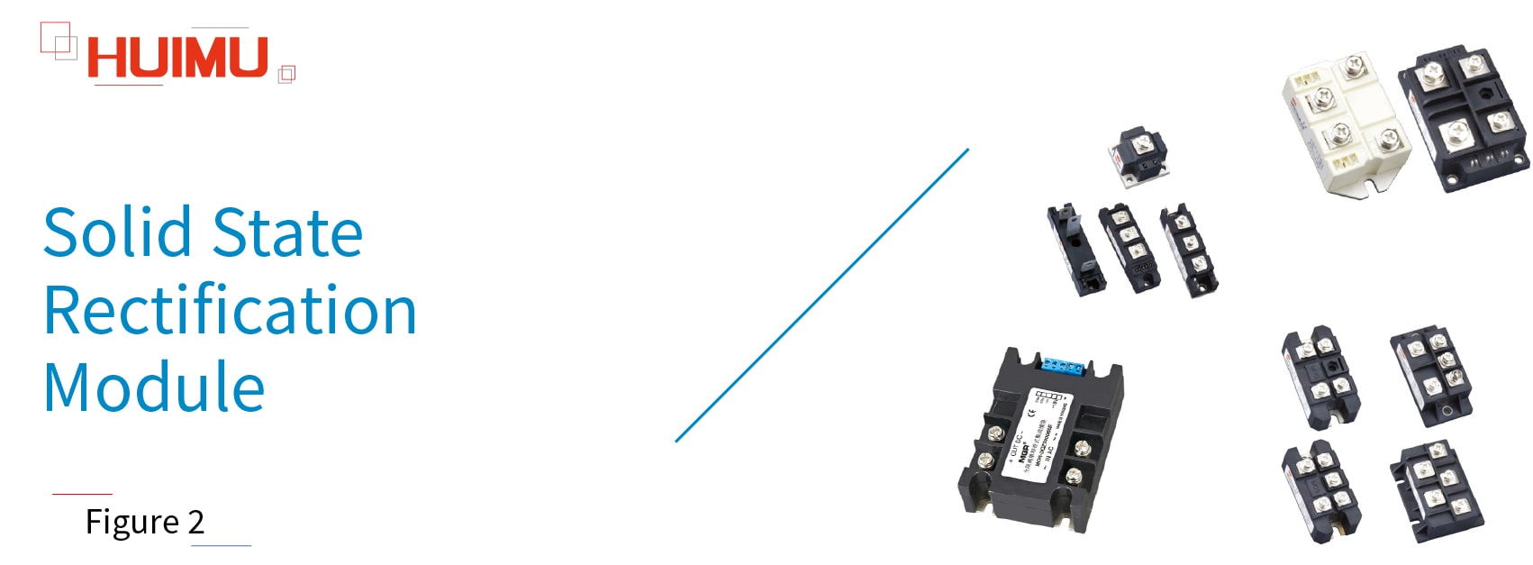
The solid state rectification module (or solid state rectifier module) uses power components (such as power diodes, power thyristors, rectifier bridges) to rectify Alternating Current (AC) into Pulsating Direct Current (Pulsating DC) or Rectified Alternating Current, whose direction (positive and negative) does not change, but the magnitude changes with time. In addition, Solid State Diodes and Rectifier Silicon are uncontrollable devices, and Semiconductor Control Rectifier and Unidirectional thyristor are controllable devices. Solid state rectification modules are widely used into various fields, such as the DC power supply of instruments, the input rectified power supply of PWM inverter, the excitation power supply of DC motor, the input rectification system of switching power supply, the soft-start capacitor charging system, the electric drive and auxiliary current, the inverter welding machine, the DC power charging system.

According to the phase, solid-state rectifier relays can be divided into: single-phase solid-state rectifier relays, three-phase solid-state rectifier relays.

According to the phase, solid-state bridge rectifiers can be divided into: single-phase solid-state bridge rectifiers, three-phase solid-state bridge rectifiers.

According to the amount of rectifier silicon (or diode), solid-state rectifier modules can be divided into: half-wave rectifier modules, full-wave rectifier modules (half-bridge rectifier modules), and full-bridge rectifier modules. The half-wave rectifier module has only one rectifier silicon (or diode), the full-wave rectifier module (half-bridge rectifier module) has two rectifier silicon (or diodes), and the full-bridge rectifier module has four rectifier silicon (or diodes). The full-wave rectifier modules have the similar function as the full-bridge rectifier modules, but the cost of the full-bridge type is higher than the full-wave type, and the requirements on the transformer are lower than the full-wave type.

According to whether the strong current parts and weak current parts are isolated, solid-state rectifier modules can be divided into fully isolated and non-fully isolated.

According to the composition of diodes and thyristors, solid-state rectifier modules can be divided into uncontrolled rectifier modules, fully-controlled rectifier modules and half-controlled rectifier modules. The output components of the uncontrolled rectifier module are completely composed of rectifier diodes. The output components of the fully controlled rectifier module are composed of thyristors. The output components of half-controlled rectification are composed of diode and thyristor.

§2. How does Power Module works

In this chapter you will learn how do electronic power modules work.

2.1 The Working Principle of Solid State Voltage Regulation Module

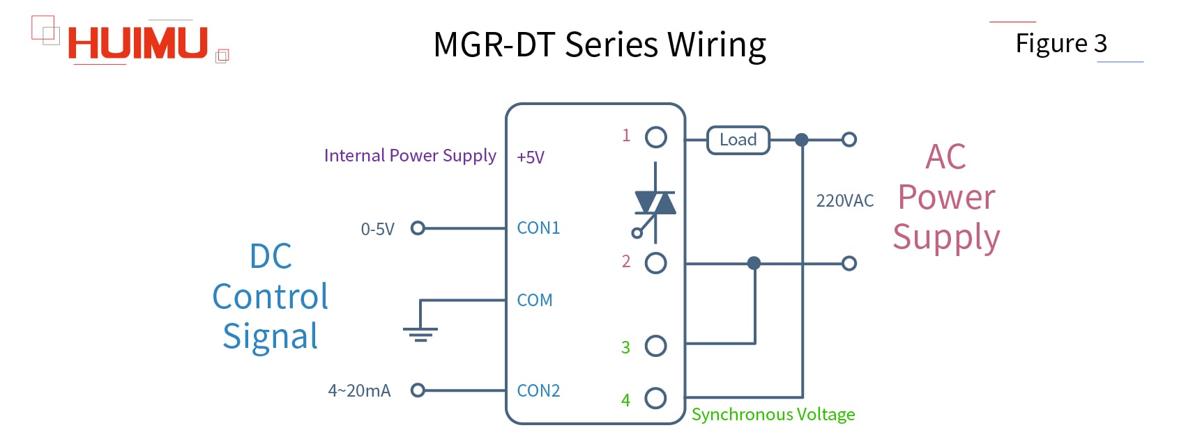
Take our MGR-DT series  single phase voltage regulation module as an example. The MGR-DT series consists of a synchronous transformer, a phase detection circuit, a phase shift trigger circuit, and a thyristor output circuit. MGR-DT accepts two control modes (automatic control and manual control), and four control signals (0-5VDC, 0-10VDC, 1-5VDC, 4-20mA). Automatic mode, that is, the control signal applied to the solid-state voltage regulator is generated by PLC or computer system. Manual control mode, that is, the 0-5VDC control signal is generated by manually controlling a potentiometer under the 5VDC internal power supply.

The wiring of MGR-DT series:
Ports 1 and 2 are the power output ports of the solid-state voltage regulator module. The load and power supplier can be directly connected to the output port of the voltage regulator module. Because the voltage and current of the inductive load are not synchronized, and will be charged and discharged during the power-on and power-off process, we will use a pure resistive load to describe the working process by default.
Copyright @ huimultd.com

Ports 3 and 4 are connected to the built-in synchronous transformer of the solid-state voltage regulator module. The role of the synchronous transformer is to provide the thyristor in the module with a signal synchronized with the AC voltage of the power supply to ensure that the load voltage can be adjusted accurately without causing output delays and voltage errors. CON1 and CON2 are input ports for automatic control signal; + 5V is the power generated inside the solid-state voltage regulator module, which is used to supply the potentiometer and connected to the high potential side of the potentiometer; COM is the common terminal, and COM port will be grounded if the automatic control mode is chosen, and will be connected to the low potential side of the potentiometer if manual control mode is selected.

The working process of MGR-DT series:
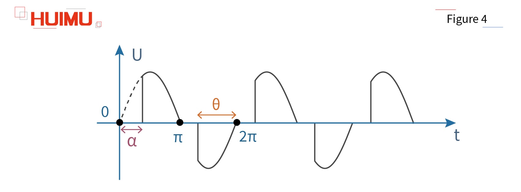
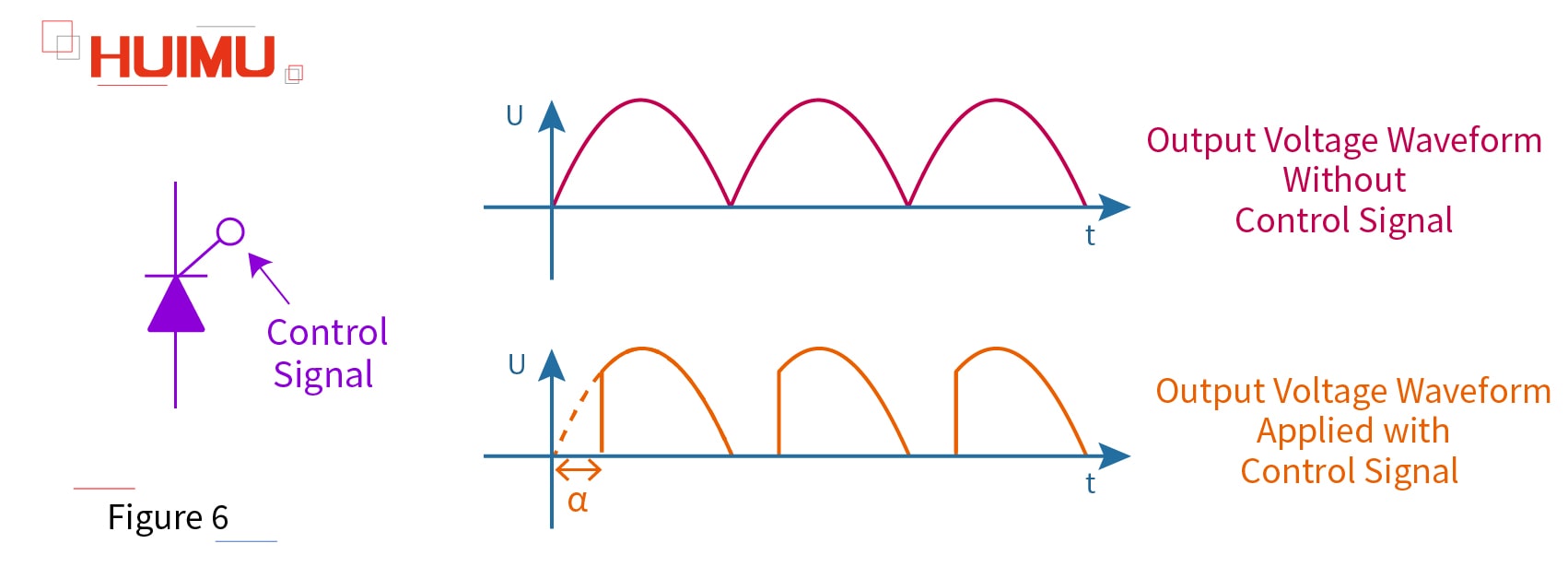
Before explaining the working principle of the voltage regulator module, we need to know that the voltage of the alternating current (AC) alternates periodically from 0 to the peak. And it is not the instantaneous voltage that does the work on the load, but the effective AC voltage which is thermodynamically equivalent to the DC voltage. By changing the time that the AC voltage does work in a cycle, it is possible to change its effective voltage value. We normally use the thyristor for voltage regulation, because it is a controllable component, and its conduction ability can be adjusted by adjusting the signal applied on its control electrode (gate). This ability can be represented by the conduction angle α on the AC voltage curve. In addition, there is a quantity corresponding to α called the control angle θ, their relationship is θ + α = π (180 °), so the larger the conduction angle, the smaller the control angle.
Copyright @ huimultd.com

We choose CON0-5VDC as the control signal, and the control voltage rises from 0 to 5VDC. Because the starting voltage (trigger voltage) of the unidirectional thyristors (SCR) is 0.8VDC, if the voltage is less than 0.8VDC, the thyristor is turned off, that is, the solid-state voltage regulating module does not work. When the voltage reaches 0.8VDC, although the transistor starts to work, its conduction angle α is 180 °, so the voltage regulator module does not output any power at this time. When the voltage is adjusted from 0.8 to 5VDC, the conduction angle α is smoothly adjusted from 180 ° to 0 °. At this time, the effective value of the output voltage is adjusted from 0 to the maximum value of the power grid. But the saturation voltage of the thyristor is 4.6VDC, so if the voltage reaches 4.6VDC, the thyristor saturates and the output voltage reaches the maximum value, at this time, no matter how much the control voltage is increased, the output voltage will not change.

2.2 The Working Principle of Solid State Rectification Module
Copyright @ huimultd.com

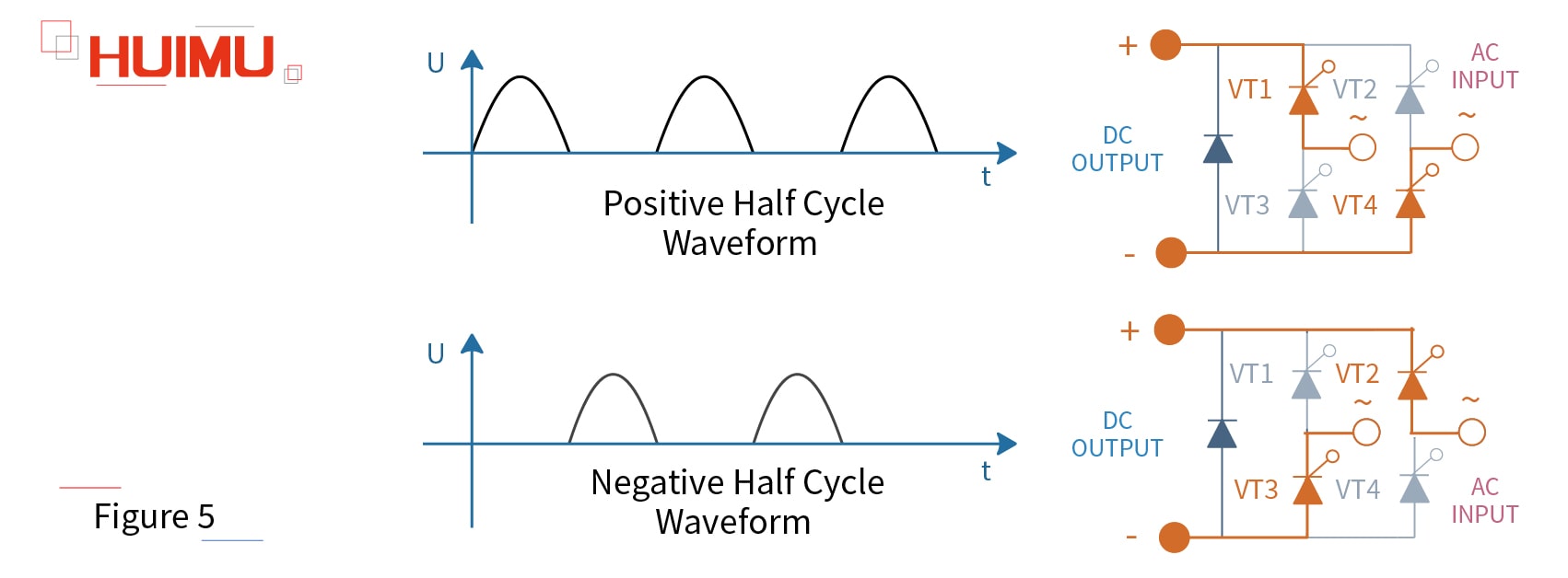
Take MHF series  single phase fully control rectifier module as an example. The MHF series rectifier module contains 4 unidirectional thyristors (SCR), VT1, VT2, VT3, VT4. And VT1 and VT4 constitute a pair of bridge arm, and VT2 and VT3 constitute another pair of bridge arm. Two pairs of bridge arms form the full bridge rectifier. When the input voltage U is in the positive half cycle, the current direction is VT1-R-VT4; when the input voltage U is in the negative half cycle, the current direction is VT2-R-VT3.
Copyright @ huimultd.com

In addition to the rectification function, we can apply a control signal to the control pole (gate) of the unidirectional thyristor. By adjusting the conduction angle α of the thyristors, its output waveform and output voltage value can be changed, which is similar to the phase-shift process of voltage regulation module.

§3. How to select the Power Module

3.1 Voltage Regulator

3.1.1 Single Phase
Standard Potentiometer Type: MGR-R series 
Industrial Potentiometer Type: MGR-HVR series 
Analog Signal/Continuous Voltage Type: MGR-1VD series 
Digital Signal/Pulse Voltage Type: MGR_DV series 
External Transformer Type: MGR-EUV series 

3.1.2 Three Phase
Basic function: MGR-SCR3_LA series 
Multiple function: MGR-SCR_LAH series 

3.2 Voltage Regulator Module

3.2.1 Single Phase
Closed-loop Feedback: MGR-DT series 
Full-isolation: MGR-DTYF series 

3.2.2 Three Phase
Full-isolation: MGR-STY series 

3.3 Phase-shift Module

3.3.1 For Solid State Relay
Single Phase: SSR-JK series 
Three Phase: SSR-3JK series 

3.3.2 For Power Thyristor Circuit
Single Channel/Single Phase: SCR-JKK, TRAIC-JKK series 
Dual Channel: SCR-JKK^2 series 
Three Channel/Three Phase: SX-JK series 

3.4 Solid State Rectifier Relay

Single Phase: MGR-ZK series 
Three Phase: MGR-3ZK series 

3.5 Solid State Bridge Rectifier

Single Phase: KBPC, QL series 
Three Phase: SQL series 

3.6 Solid State Rectifier Module

3.6.1 Welding Machine Rectifier Module
MT, MF, MD series: MT, MF, MD 

3.6.2 Solid State Thyristor/Diode Rectifier Module
Solid State Thyristor Rectifier Module: MTC, MTA, MTK, MTX series 
Solid State Diode Rectifier Module: MDC, MDA, MDK, MDX series 
Solid State Hybrid Rectifier Module: MFC, MFA, MFK, MFX series 

3.6.3 Full Isolation Single Phase Fully-Controlled Bridge Rectifier Module
MGR-DQZ series: MGR-DQZ 

3.6.4 Single Phase/Three Phase Bridge Rectifier Module
Single Phase: MDQ series 
Three Phase: MDS series 

3.6.5 Fully-controlled/Half-controlled Bridge Rectifier Module
Single Phase: MFQ, MTF, MHF series 
Three Phase: MTQ, MFS, series 

Copyright @ huimultd.com

https://electronics.huimultd.com/Blog/Turbo_Mode/

HOW TO VIEW OUR PAGES IN YANDEX TURBO MODE?

INTRODUCTION:

The Information Center now fully supports the Yandex Turbo Mode, so that even if your network is not optimistic, you can visit our information center very smoothly to learn everything about solid state relays.
Through this article you will learn what is the turbo mode? How to browse turbo pages?

You can quickly navigate to the chapters you are interested in through the Directory below, and the Quick Navigator on the right side of the browser.

CONTENTS


§1. What is the Turbo Mode 

 §2. How to browse Turbo Pages

§1. What is the Turbo Mode

Turbo Mode is a web acceleration technology developed by Opera. By reducing the content of web pages by up to 75%, users who connect 3G or low quality public WIFI networks get an excellent browsing experience. 2016 Yandex launched the Turbo Mode in the Yandex browser.

There are two thresholds that determine when Turbo mode switches on and off:

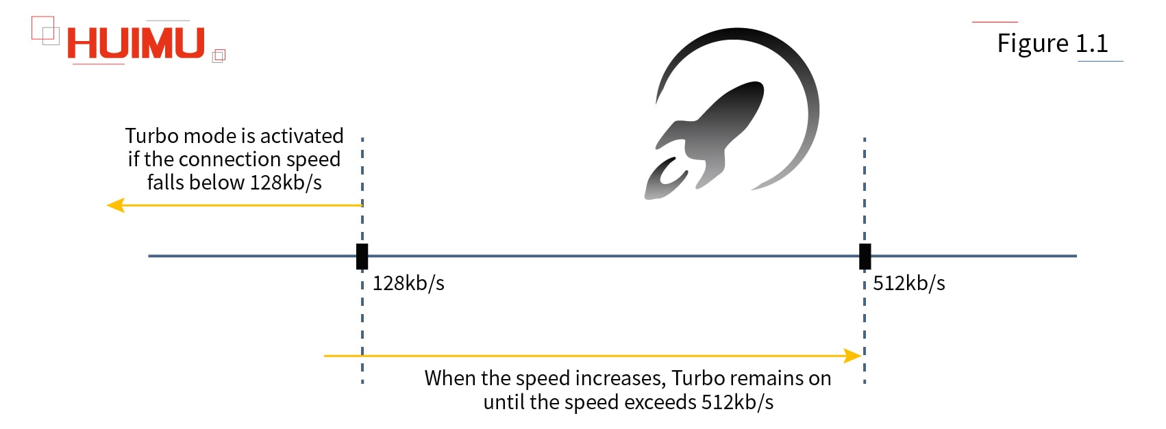
1) Turbo mode is enabled when connection speed falls below 128 Kbit/s, and remains on until the speed exceeds 512 Kbit/s.
2) When the connection speed exceeds 512 Kbit/s, Turbo automatically switches off (and the icon in the SmartBox disappears). Turbo mode remains off until the speed falls below 128 Kbit/s.

There are two thresholds that determine when Turbo mode switches on and off. More detail via www.@huimultd.com

We optimized the HTML code for each article and image according to Yandex's requirements.
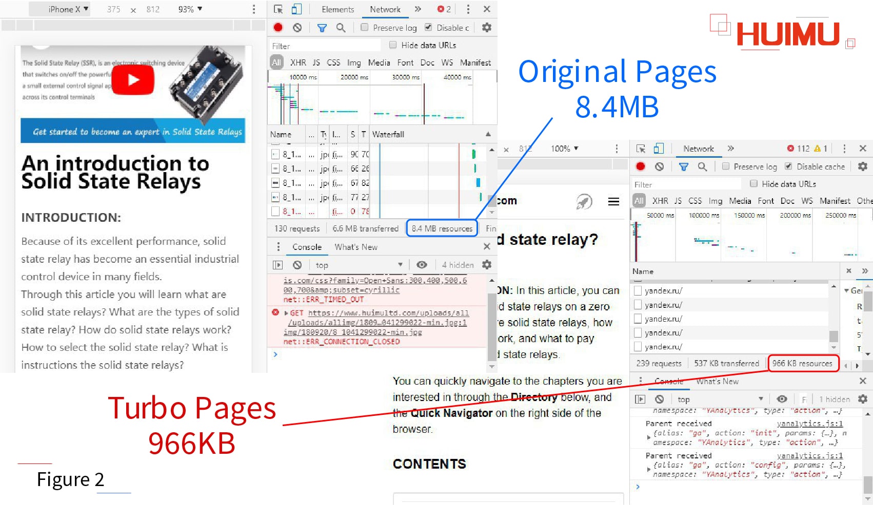
Take What is the solid state relay? as an example, the size of the article has been reduced from 8.4MB to 966KB (a reduction of 88%). Therefore, Turbo Mode allows everyone to browse our Information Center with the fastest speed of loading and the least amount of traffic.

The content of web pages will be reduced up to 75% More detail via www.@huimultd.com

§2. How to browse Turbo Pages

In the following video, I will use our website as a demo to tell you how to access the Turbo page.

Demo device information:

Device Name: HUAWEI MATE10

Device System: EMUI 9.1.0.321(C00E320R2P1) GPU Turbo

Device Language: English

Internet Service Provider: China Mobile

Internet Browser: Yandex Browser

Download Yandex Browser

1. Download and open the Yandex Browser

Open Yandex Browser

2. Select Yandex search engine

Enter keywords to search

3. Enter keywords such as "HUIMU Industrial"

Find the Page with Turbo mode

4. Open the page that supports Turbo Mode

Enter the Page with Turbo mode

5. Turbo page menu

View source page

6. Turn off Turbo mode

How to purchase the real MGR/mager solid state relay

How to purchase the real MGR/mager solid state relay

INTRODUCTION:

"We always believe that a manufacturer or company with excellent quality and service does not have any need to use the brand effect of other companies to promote and sell its products."
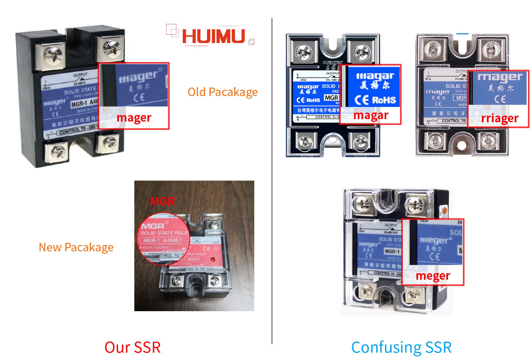
 According to customer feedback, they find some companies with confusing brand name and logos (such as meger, rriager, magar, megar, 111agar, which looks similar as mager) on e-commerce platforms, like ebay, alibaba, taobao, tmall. It has been verified that most of these companies were established after 2014, and sell products with the similar appearance and label to ours. Optimistically speaking, their existence also reflects that our products are widely recognized in the market. In order to avoid damage to our brand image, since 2017, we changed the logo from mager to MGR, and redesigned the labels and packaging of all products, and further improved the quality of our products.
Although we have been using positive legal measures to protect our customers from counterfeit and shoddy products, we also hope to help our customers to keep away with these phoneys by better understand our brand and products.

Through this article, you will learn about what is our brand history? What are the purchase channels for our solid state relays? What are the characteristics of our solid state relays? How to avoid the confusing product?

You can quickly navigate to the chapters you are interested in through the Directory below, and the Quick Navigator on the right side of the browser.

1. Introduction of Our Brand

Brand Name

●   Chinese full name: 乐清市美格尔电子电器有限公司;
●   Chinese abbreviation:美格尔
●   English full name:YUEQING MGR ELECTRONIC AND ELECTRICAL CO., LTD.
●   English abbreviation: MGR, or MAGER.
●   Other avaiLabel English name:YUEQING MEIGEER ELECTRONIC ELECTRIC CO., LTD.; YUEQING MEIGEER ELECTRONIC & ELECTRIC APPLIANCES CO., LTD.; YUEQING MEIGEER ELECTRONICS AND ELECTRIC CO., LTD.; YUEQING MEIGEER ELECTRONIC APPLIANCE CO., LTD.; YUEQING MEIGEER ELECTRON ELECTRICAL CO., LTD.; YUEQING MAGER ELECTRON ELECTRICAL CO., LTD.; YUEQING MGR ELECTRON ELECTRICAL CO., LTD.
According to Chinese law, English names can be changed and used at will, as long as they conform to the translation principles. Therefore, Chinese companies may have many English names in addition to the only Chinese name, and these English names vary according to the translation methods of different organizations (which also explains why we have so many English names). However, the English name cannot be officially registered in the industrial and commercial administration of China, nor is it regulated or restricted by Chinese law. Only the Chinese name enjoys all the rights of the company and the brand. Our Chinese name has never changed since it was officially registered in 2001, and we have not registered other branches. Therefore, when choosing a solid state relay, please look for our Chinese name: 乐清市美格尔电子电器有限公司 (hereinafter referred to as MGR, we, us or our). Although the production line of MGR is constantly expanding, its registered place and site have never left Yueqing City, China. (P.S. Yueqing City is a county-level city in Wenzhou City). If you meet other companies that contain meigeer, like Taiwan meigeer (twmgr), Shenzhen meigeer, Hongkong meigeer, Zhejiang meigeer, Shanghai meigeer, Wenzhou meigeer, Yueqing meigeer solid state relay, Yueqing meigeer relay, meigeer electricals (chmgr) and etc., we can tell you with certainty that they have no relationship with us.

Brand History

Since the 1990s, we have been engaged in the development and manufacture of electronic products and solid state relays.

In 2001, we officially registered YUEQING MEIGEER ELECTRONIC ELECTRIC CO., LTD. and started to provide solid state relays for companies across China.

In 2004, we used mager as an English trademark as products flowed into overseas markets through various foreign trade companies.

In 2008, we obtained ISO9001: 2000 quality management system certification. And our headquarters moved to the Beibaixiang Industrial Park.

In 2017, to avoid brand damage and better protect consumer rights, we used a more recognizable logo MGR.

In 2018, MGR cooperated deeply with HUIMU Trade to provide high quality MGR solid state relays and services to the world through HUIMU Industrial. Since then, MGR officially entered the overseas market.

In 2019, due to production needs, the MGR headquarters moved to the newly built MGR building, and MGR still plans to further expand the production line.

So far, we have sold millions of solid state relays. And we have been widely praised by users at home and abroad due to the high quality, the extremely low failure rate of our products. In the future, we will strive for excellence and work harder to help more customers.

2. How to distinguish our solid state relays

First, let us compare our products to those confusing products. Obviously, their logo is so similar to ours, even the design of the label is exactly the same, so that it is hard to distinguish from them at first sight. Actually, most of these companies were established between 2014-2018. Therefore, we are curious about what happened in 2014 and we would like to know what led to dozens of such companies appeared in a short period of time. In order to avoid damage to the brand image and protect the rights and interests of users, from 2017, we redesigned the packaging and labeling, and further upgraded the brand image, product quality and service.

Our SSR vs Confusing SSR. More detail via www.@huimultd.com

The comparison of the old and new designs is shown below.

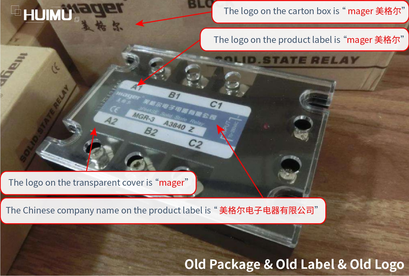
Old Package & Old Label: The Logo is "mager 美格尔";The Chinese Company Name is "美格尔电子电器有限公司"; The Origin is "MADE IN CHINA".

Old Package & Old Label & Old Logo. More detail via www.@huimultd.com

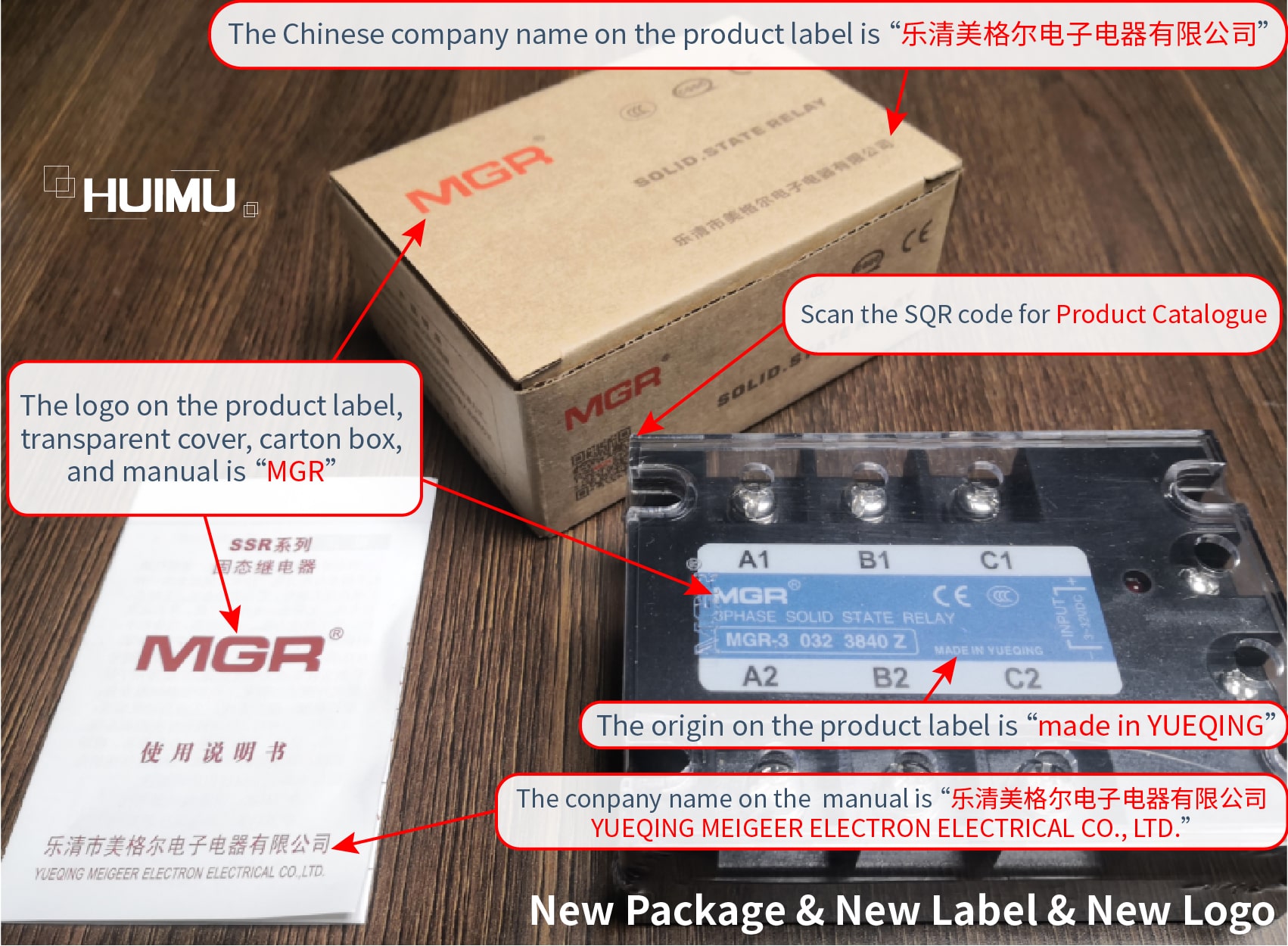
New Package & New Logo: The Logo is three simple and showy letters "MGR", no any Chinese in it;The Chinese Company Name is "乐清美格尔电子电器有限公司", which is our full company name; The English Company Name is "YUEQING MEIGEER ELECTRON ELECTRICAL CO., LTD."; The Origin is "MADE IN YUEQING".

New Package & New Label & New Logo. More detail via www.@huimultd.com

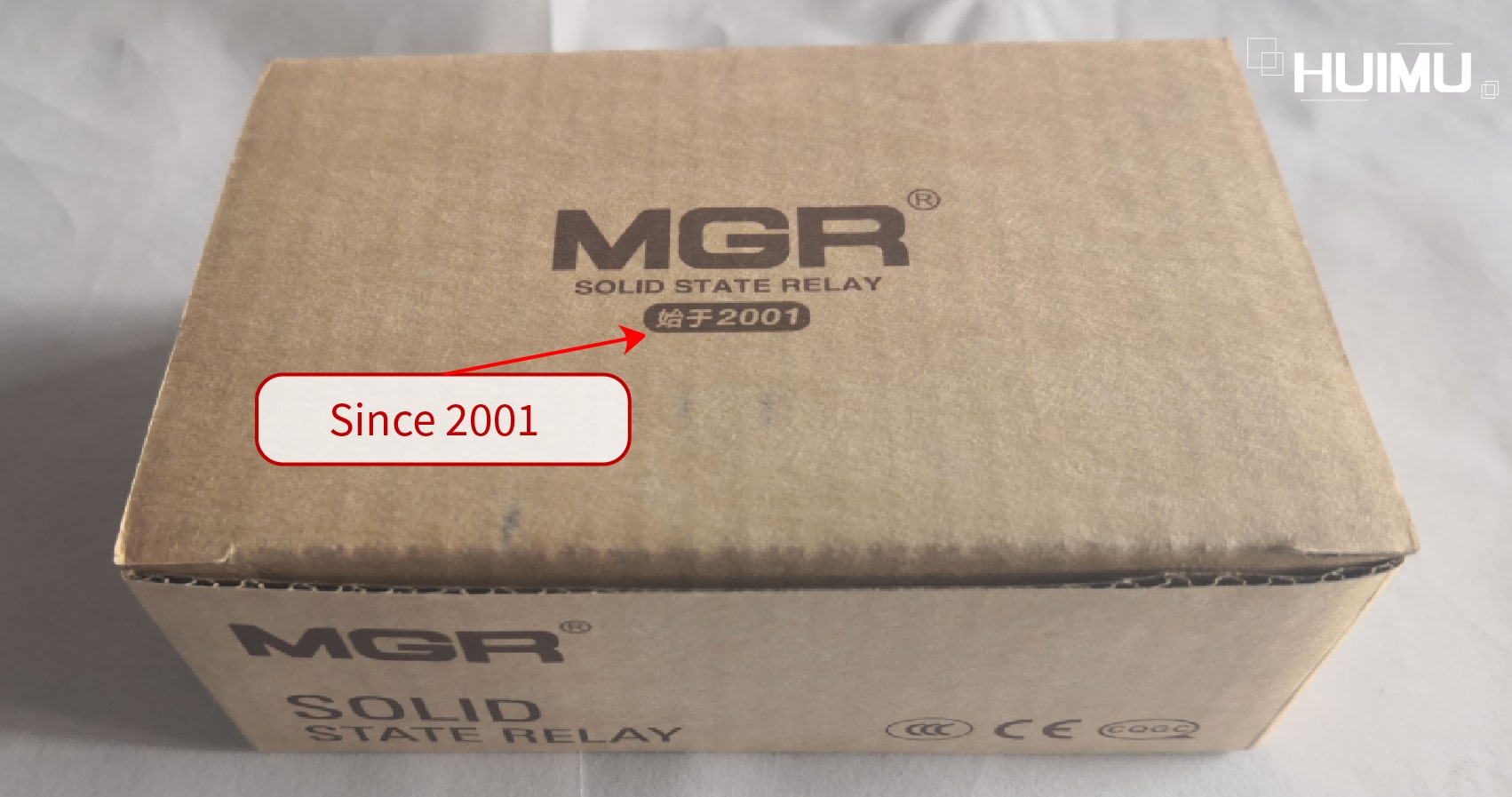
On some cartons, we will print "始于2001" (which means "since 2001").

Since 2001. More detail via www.@huimultd.com

3. Where to buy our solid state relays

Official Channel

If you are in China, you can directly contact MGR.
●   Tel: 0086-0577-62875133
●   Email: mager518@yahoo.com.cn
●   Website: www.mgr.topwww.mager.cn
●   Add:
-No.306-308 Baixiang Avenue, Beibaixiang Industrial Park, Wenzhou, Zhejiang, China (MGR Factory)
-No.150 Malujiao East Road, Malujiao Village Wenzhou, Zhejiang, China (MGR Office Building)
●   Online Shop:
MGR has the only one Online Shop on the 1688.com, the site is:
https://yqmeigeer.1688.com
Except it, MGR does not have any online stores on any E-commerce platforms, such as eBay, amazon, etc.

Copyright @ huimultd.com

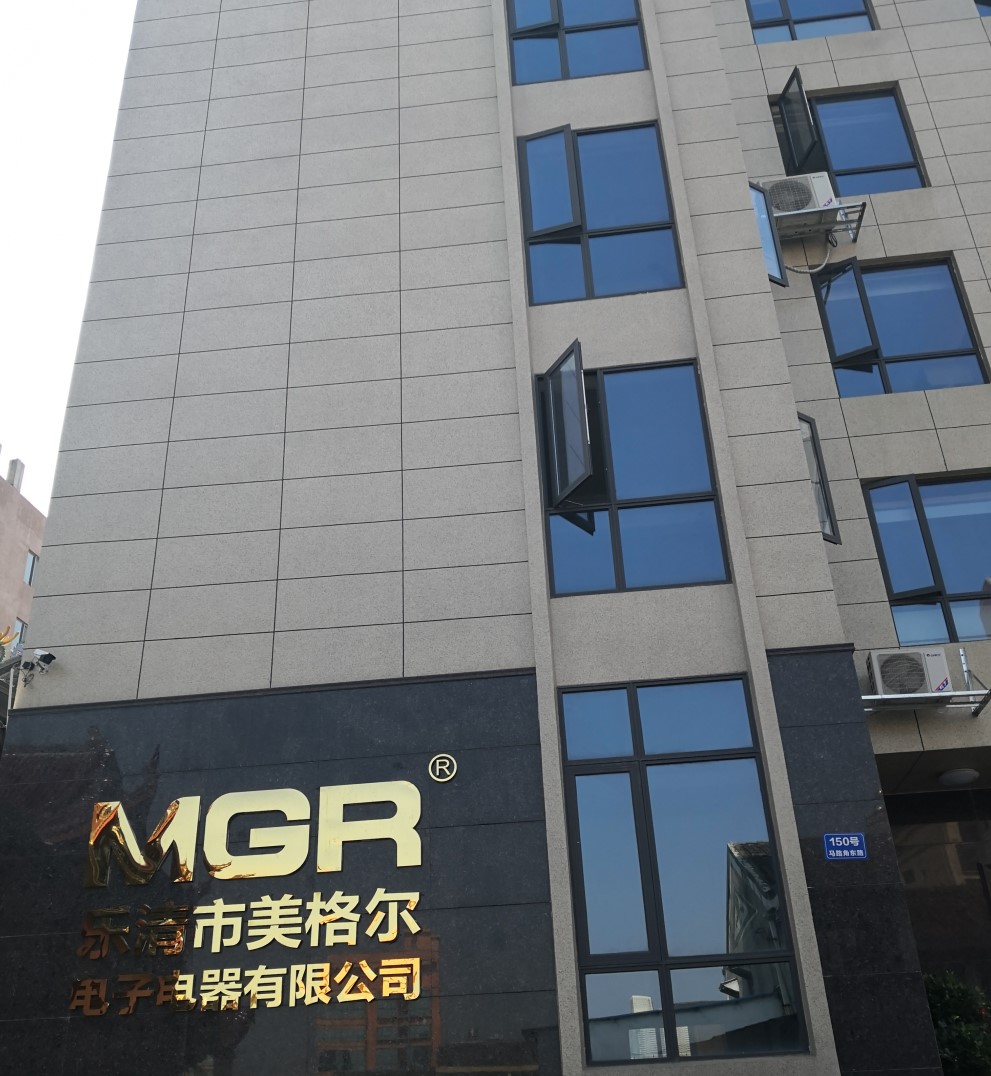
MGR Building

If you are not in China, you can contact HUIMU Industrial.
●   Tel: 0086-0577-62698923
●   Email: sales@huimultd.com
●   Website:
-Main domain: www.huimultd.com
-Sub domains: electricals.huimultd.com, electronics.huimultd.com, instruments.huimultd.com
●   Add: No.266 Liujiang Road, Wenzhou, Zhejiang, China (HUIMU Headquarter)
●   Online Shop:
Although HUIMU Industrial has registered many online shops, it is only to prevent others from registering maliciously and is not used for actual operations.

Copyright @ huimultd.com

HUIMU Industrial Headquarters

Third Party Channel

●   You can get our products through distributors. These excellent distributors can provide the same technical service and support as ours.
●   You can also get our products through retailers. Retailers will provide our services and support indirectly.
●   Our products will also enter the market through OEM and ODM, but these products are only subject to the supervision and management of the brand owners. We are only responsible to the brand owners, and you cannot get any help from us.

Copyright @ huimultd.com

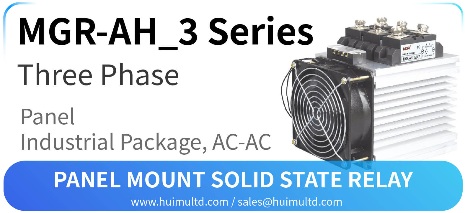
MGR-AH_3 Series Panel Mount Solid State Relay
  MGR-AH_3 Series Panel Mount Solid State Relay [All the information on this website is for reference only, and the actual product and the a...