§1. How to wire AC Reversible-motor Solid State Relay
-AC Bi-directional Motor Direction Controller Wiring Diagram
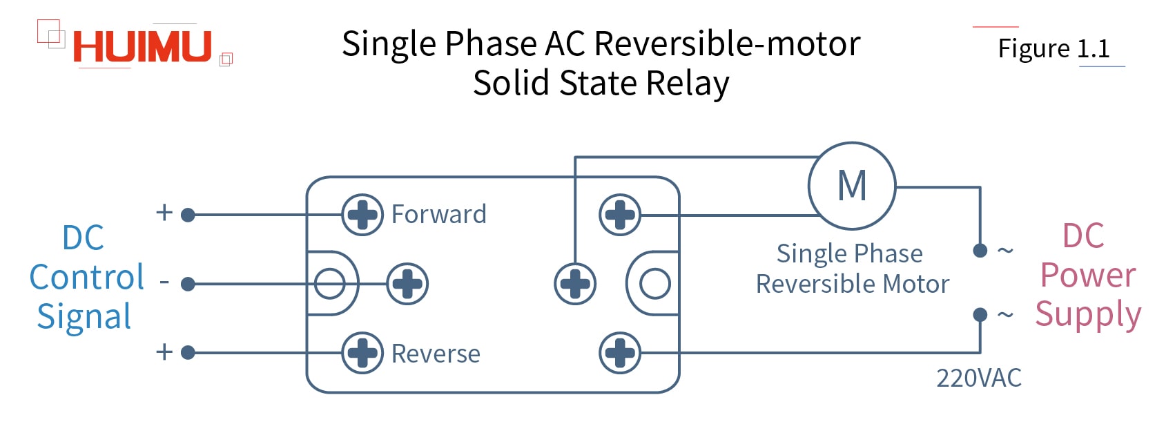
1.1 Single Phase AC Reversible-motor Solid State Relay
MGR-1M Series

The single phase AC reversible-motor solid state relay is a single phase forward and reverse switch for AC electric motor, which uses the DC control signal to control the single phase AC forward-reverse motor. The three terminals input circuit of this single phase AC motor direction control relay is connected to the DC control signal, two of these terminals are used to control the forward rotation and reverse rotation of the single phase AC bi-directional motor. The three terminals output circuit of the single phase AC forward reverse switch is connected to the single-phase AC power supply and the single phase AC motor. Two of single phase reversible motor terminals are used to control the rotation of the single phase AC reverse electric motor.
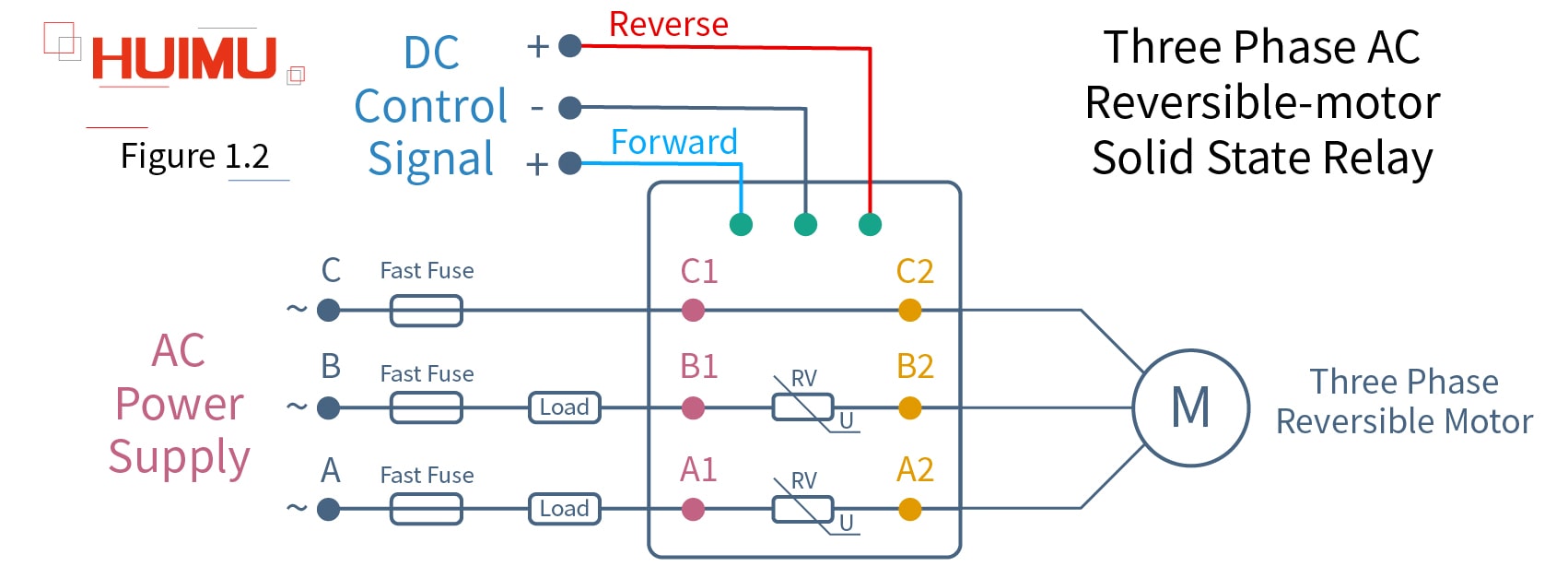
1.2 Three Phase AC Reversible-motor Solid State Relay
MGR-3M Series

The three phase AC reversible-motor solid state relay is a three phase forward and reverse switch for AC electric motor, which uses the DC control signal to control the three phase AC forward-reverse motor. The three-terminal input circuit of this three phase AC motor direction control relay is connected to the DC control signal, two of these terminals are used to control the forward and reverse rotation of the three phase AC bi-directional motor. The A1, B1, C1 terminals of the electric motor reversing switch output circuit are connected to three-phase AC power supply; the A2, B2, C2 terminals are connected to three-phase AC reverse electric motor.
§2. How to wire DC Reversible-Motor Solid State Relay
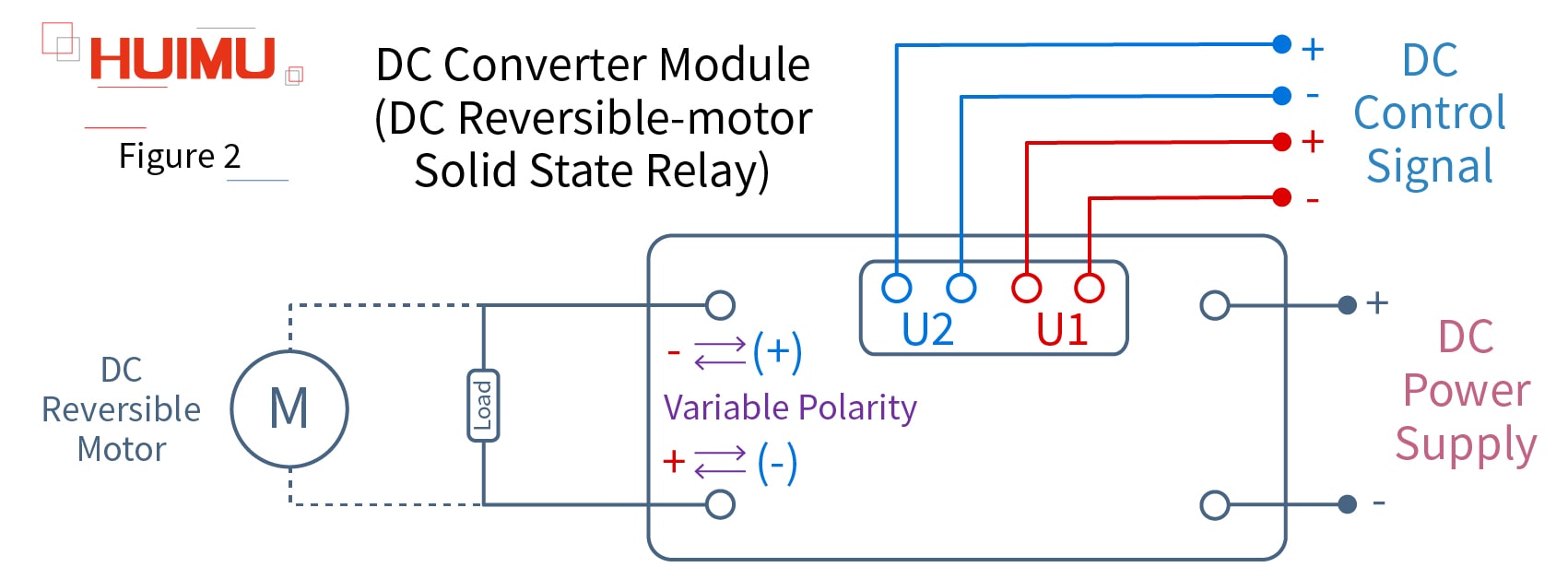
-DC Bi-directional Motor Direction Controller Wiring Diagram
MGR-DHK Series

The DC reversible-motor solid state relay is a DC forward and reverse switch for DC electric motor, which uses the DC control signal to control the DC forward-reverse motor. The four-terminal input circuit of this DC motor direction control relay is connected to the DC control signal. These control signal terminals are divided into U1 and U2, which are respectively used to control the forward and reverse rotation of the DC bidirectional motor. The output circuit of this DC electric motor reversing switch is connected to the DC load and DC reversing motor. The polarity of the two terminals connected to the DC reverse electric motor can be exchanged according to the DC control signal. When U1 is turned on, the output current flows from the "+" port to the "-" port. When U2 is turned on, the output current flows from the "(+)" port to the "(-)" port.
§3. How to wire DC Governor
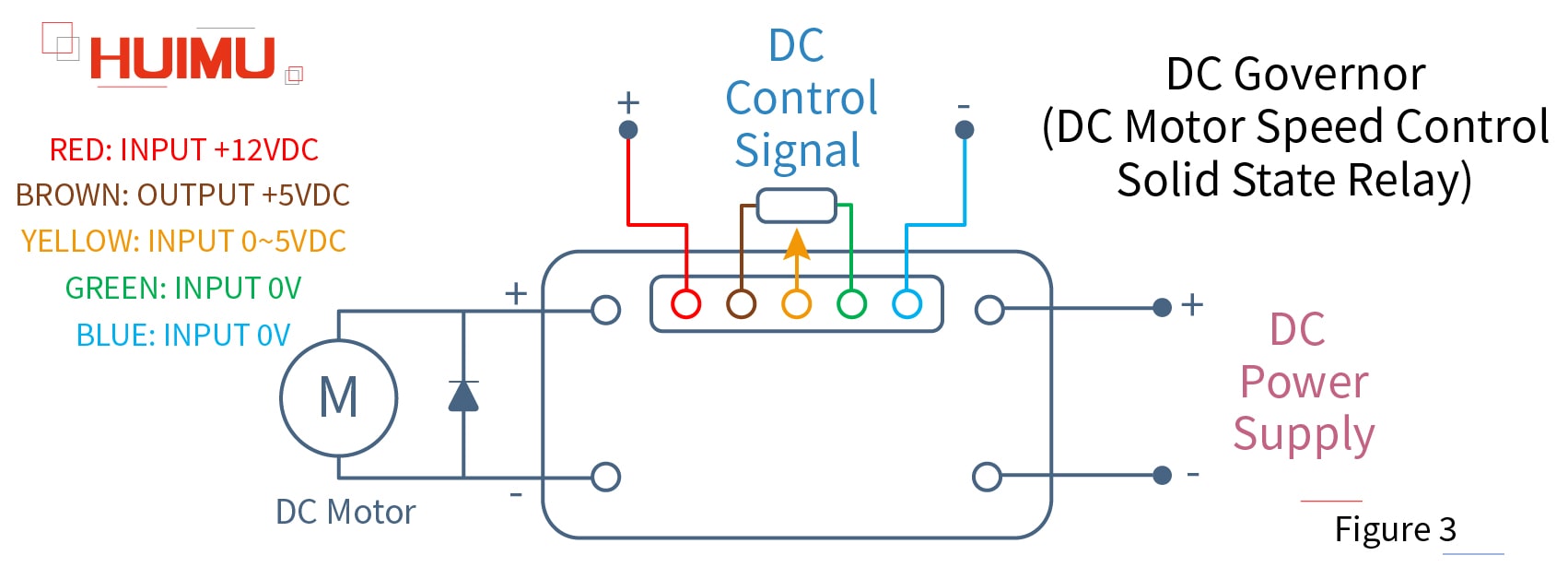
-DC Motor Speed Control Solid State Relay Wiring Diagram
MGR-DTSV Series

The DC motor speed control solid state relay is a variable speed control for DC electric motor, which can control the rotational speed of the DC electric motor. The input circuit of the DC thyristor motor speed control switch is connected to the DC control signal—RED cable and BLUE cable provide the power for the input circuit; and the BRWON cable, YELLOW cable and GREEN cable adjust the speed of the DC motor by controlling the varistor. The output circuit of the DC speed controller is connected to the DC power supply.

